AE-98
Introduction
Recommended Pit Ventilation Rates
   Winter rates
   Summer rates
Pit Ventilation Systems
   Exhaust duct system
   Exhaust annex system
Exhausting Pit Ventilation Air
Pit Ventilation Design-Example Problems
   Example problem A (Exhaust duct system for total-slotted
      farrowing house)
   Example problem B (Exhaust duct system for partly-slotted
      nursery building)
   Example problem C (Exhaust annex system for total-slotted
      farrowing/gestation building)
Summary
   Related publications
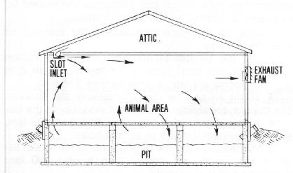
The ventilation system in an environmentally controlled slotted-floor livestock building should provide for ventilation of the manure pit as well as the animal area. Pit ventilation helps prevent manure gases from being drawn into the animal area, reduces odor levels, permits more uniform air distribution, and helps in warming and drying the floor. Therefore, all slotted-floor buildings will likely benefit from pit ventilation, even though waste may be removed frequently by flushing or scraping (Figure 1).
This publication deals with manure pit ventilation system design and operation. Discussed are proper confinement ventilation rates, the two presently-recommended pit ventilation systems, design alternatives and exhaust system considerations. The information presented should be valuable to the livestock producer who is planning a new facility or desiring to evaluate his present ventilation system.
A livestock building ventilation system provides for moisture and odor control in winter and for heat control the rest of the year. Pit ventilation is designed only for moisture and odor control.
Table 1 gives the recommended ventilation rates for swine and dairy animals in confinement. Moving air through a slotted floor at rates higher than these will not appreciably improve odor control and could cause the animals to become chilled.
                                            Cold weather rates
                                  -------------------------------------
                                     Moisture control* on-
				  -------------------------		     Mild        Hot
                                  Fully     Partly   Solid      Odor       weather     weather
  Type of animal                  slotted   slotted  floor      control     rates       rates
------------------------------------------------------------------------------------------------
                                                  cubic feet per minute
  Swine
   Sow and litter                  10      1 7          20      35            80         325
   Pre-nursery pig (12-30 lbs.)     1.0      1.6         2       3.5          10          25
   Nursery pig (30-75 lbs.)         1.5      2.5         3       5            15          35
   Growing pig (75-150 lbs.)        3.5      5.5         7      10            24          75
   Finishing hog (150-220 lbs.)     5        8          10      18            35         120
   Gestating sow (325 lbs.)         6       10          12      20            40         150
   Boar (400 lbs.)                  7       12          14      24            50         180
  Dairy
   Cow                             16.5     28          33      50           130         600
   Gait                             5        8.5        10      16            25         150
------------------------------------------------------------------------------------------------
   *Ventilate no lower than this rate it unvented heaters are used.
In winter, livestock buildings are ventilated primarily to remove moisture, with additional ventilation sometimes provided to lower odor levels. Pit ventilation is the most beneficial in winter, because it helps insure good air distribution at the low air flow rates recommended in cold weather.
Livestock productivity should not be adversely affected by higher odor levels when the building's ventilation system is operated at the cold weather moisture-control rates given in Table 1. In addition, these lower rates can result in significant fuel savings, since less heat is lost through the ventilation system. As to how significant the energy savings, consider that on a typical winter day, every extra cfm (cubic foot per minute) of air exhausted from a farrowing house carries with it over 50 BTUs of heat per hour.
One way to improve working conditions (less odor) while minimizing heat loss through the ventilation system is to use a dual, cold-weather ventilation rate that provides additional air to remove odor only when persons are in the building. The fan used to supply air at the recommended moisture control rate is run continuously, while the fan used to provide additional air for odor control is operated with a manual switch or a timer. And if a thermostat is wired in parallel so a temperature rise activates it, this same odor control fan can also become a part of the mild and hot weather ventilation system.
During summer, when ventilation rates are normally higher for heat removal, and sidewall as well as pit fans are running, more pit gases will diffuse up through the slotted floor. This seldom creates a problem, however, because the volume of fresh air being drawn through the building is usually large enough to dilute the gases, thus controlling the odor level.
Two types of pit ventilation are recommended today: (1) the exhaust duct system, in which a duct runs the length of the pit having small openings spaced at intervals to allow air to be drawn from the pit; and (2) exhaust annex system, in which one or more fans are located along the outside pit wall. Regardless of the system used, allow at least 12 inches clearance between the bottom of the slat support beams and the liquid manure surface.
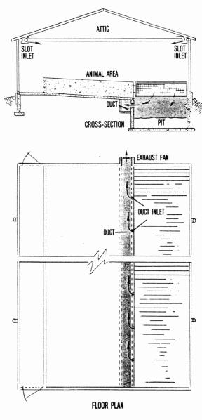
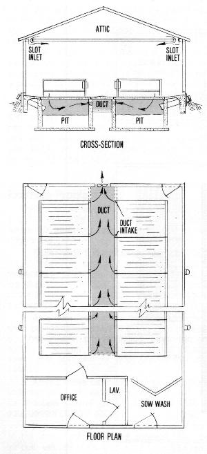
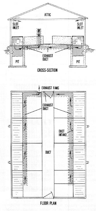
The exhaust duct system, although the more expensive of the two, provides better performance. The duct is usually placed under a center aisle in a total-slotted-floor building (Figure 2) or under the floor adjacent to the pit in a partly-slotted-floor building (Figure 3).
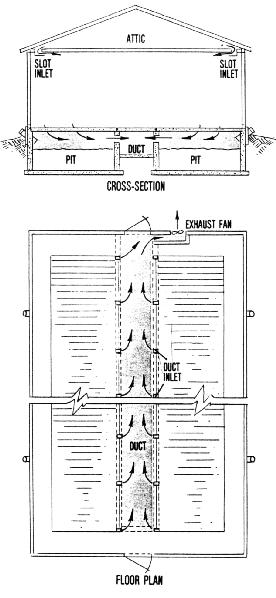
Correct sizing of the duct and duct inlet holes is critical to uniform pit ventilation. The duct area is based on an air speed of 600 feet per minute (fpm), and the size of the in let holes is based on 800 fpm. Too small a duct or the wrong-sized duct openings results in poor air distribution.
Table 2 gives the minimum cross-sectional duct areas and corresponding duct wall dimensions for various pit fan capacities. Somewhat larger sizes will not affect ventilation. Table 3 shows the required inlet area per pen, number of openings and their dimensions at different air flow rates. These sizes are critical and should not be varied.
		  	 Dimensions if duct is-
  Pit fan      Minimum  ------------------------
  capacity     duct area  Rectangular   Round
-------------------------------------------------
  cu. ft./min.  sq. in.    in. x in.   in. diam.

     200          48       6  x 8         8
     250          60       8  x 8         9
     300          72       8  x 9        10
     350          84       9 x 10        10
     400          96      10 x 11        12
     500         120      10 x 12        14
     600         144      12 x 12        14
     700         173      12 x 14        15
     800         192      14 x 14        16
     900         216      14 x 16        18
   1,000         240      14 x 16        18
   1.200         288      16 x 18
   1,400         336      16 x 21
   1,600         384      16 x 24
   2,000         480      20 x 24
   2,500         600      20 x 30
   3,000         720      24 x 30
   3,500         840      26 x 32
   4,000         900      30 x 30
   4,500       1,080      30 x 36
   5,000       1,200      30 x 40
   6,000       1,440      36 x 40
----------------------------------------------
  *  Based on a duct air speed of 600 fpm
  Per pen or stall
-------------------  Dimensions if opening is-
Air  Total   No. of  ---------------------------
flow  area  openings  Rectangular      Round
-------------------------------------------------
cfm   sq.in.           in. x in.     in. diam.

 20    3.75    1      2 x 2            2 1/4
 25    4.5     1      2 x 3 1/4        2 1/2
 30    5.4     1      2 x 2 3/4	       2 3/4
 35    6.25    1      2 x 3 1/4        3
 40    7.25    1      2 x 3 3/4        3 1/2
 60   10.75    1      3 x 3 3/4        3 3/4
 80   14.5     1      3 x 5
100   18       1      4 x 4 1/2
125   22.5     1      4 x 5 3/4
150   27       1      4 x 6 3/4
200   36       1      4 x 9
250   45       1      4 x 10 1/4
300   54       2      4 x 6 3/4 each
350   63       2      4 x 8 each
400   72       2      4 x 9 each
450   81       2      4 X 10 1/4 each
500   90       2      4 x 11 1/4 each
550   99       2      4 x 12 1/2 each
600  108       2      4 x 13 1/2 each
700  126       2      4 x 15 3/4  each
-------------------------------------------------
   * Based on an air speed of 800 fpm through the opening
Spacing of duct inlets depends on the ventilation rate needed per pen or crate and the size of the inlets. How to calculate proper intake spacing is illustrated in the examples at the end of this publication. As a general rule, however, space ducts across a building such that no portion of the slotted floor is more than 20 feet (preferably 15 feet) away from a duct air inlet.
The pit ventilation duct is usually a concrete or plywood channel, although many types of construction material will work if the overall design is correct. In small buildings, such as a 10-sow farrowing house, an 8- to 12-inch plastic sewer pipe serves adequately as a duct. In very long buildings, a fan can be placed at each end or at the center of the duct to decrease the volume of air it must carry, thus permitting use of a smaller duct area. For most uniform ventilation, no point in the duct should be further than about 80 feet from a pit exhaust fan.
After an exhaust duct system has been installed but before animals begin using the building, each duct inlet hole should be checked to make sure that air flow is the same, no matter how far the inlet is from the fan. To make this check and to adjust inlets for uniform flow rate, follow this procedure developed by engineers at North Carolina State University:
The exhaust annex system is commonly used in total-slotted-floor buildings. It does not provide as uniform an air distribution through the floor as a duct system but is cheaper to install.
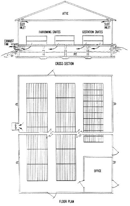
The fan is housed in a small annex or `doghouse adjacent to the pit, and pulls air into the annex through a slot in the pit wall. The annex is usually on the outside of the building wall (Figure 4), but is sometimes constructed on the inside (Figure 5).
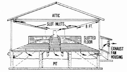
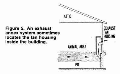
Table 4 shows the minimum slot areas and corresponding slot dimensions to maintain an 800 fpm air velocity for various pit fan capacities. Slightly larger slot openings should not significantly affect performance.
		        Dimensions of opening is-
 Pit fan     Minimum    ---------------------------
 capacity    slot area  Rectangular      Round
---------------------------------------------------
 cu. ft./min.  sq.in.     in. x in.     in. diam.

     400           72      4 x 18         10
     500           90      4 x 23         12
     600          108      4 x 27         12
     700          126      4 x 32
     BOO          144      4 x 36
     900          162      6 x 27
   1.000          180      6 x 30
   1,100          198      6 x 33
   1,200          216      6 x 36
   1,300          234      6 x 39
   1,400          252      6 x 42
   1,500          270      8 x 34
   1,600          288      8 x 36
   1,800          324      8 x 42
   2,000          360     12 x 30
   2.500          450     12 x 38
   3,000          540     12 x 45
   3,500          630     18 x 36
   4,000          720     18 x 40
   4,500          810     24 x 36
   5,000          900     24 x 40
---------------------------------------------------
     *Based on an air speed of 800 fpm
If the annex is to be placed outside the pit wall, construction can be such that the full pit depth extends into the annex. In this case, the annex can serve as a manure pump-out area as well as the pit fan housing. This permits use of a large chopper agitator-type pump, which is much more effective in agitating and removing settled manure solids than the standard vacuum tank wagon.
The 12-inch minimum space between the bottom of the slat support beams and surface of the manure is especially important with an exhaust annex system, since air must be drawn a great distance. It is also important that the annex be located so no point in the pit is further than about 50 feet from it.
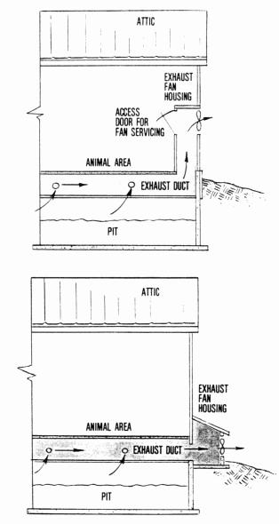
Fan housings for exhaust duct and exhaust annex systems are similar. Both systems either bring the air up from the pit through a duct for exhaust out a sidewall or endwall of the building (Figure 6A) or exhaust directly from a fan housing located at ground level (Figure 6B). Table 5 gives the housing dimensions needed for various fan diameters.
                      Fan house dimensions
	Fan	      ---------------------
      diameter**       X axis     Y axis
--------------------------------------------
         in.

     14 or smaller    1'-10"       2-4"
         16           2'
         18           2'
         24           2'- 8"
         36           3'- 4"
--------------------------------------------
   *From university of North Carolina Publication 581
   **See AE-96 for proper fan diameters.
If livestock waste odor is a problem, consider discharging the pit ventilation air from a point high on the sidewall, since odors are likely to be dissipated faster than if discharged at ground level. Some farmers carry this a step further by adding chimney vents to exhaust even higher (Figure 7), In many heavily-populated areas of Europe, farmers exhaust all ventilation air at roof level.
If using a chimney vent, locate it on the upwind side of the building for maximum air dispersion, with the top at least as high as the eave. The chimney should be about 50 percent larger than the fan diameter (limit velocity to no more than 1000 fpm). Locate a `weep' (drain) hole at the base of the vent so condensation or rainwater cannot collect. Since the pit fan is operating at all times, frost formation and snow blow-in should not be a problem.
An elevated exhaust has an added benefit if variable-speed fans are used. Since these fans do not perform well against high pressures when operated at low speed, the chimney protects the fans from wind, allowing them to supply a more uniform ventilation rate.
A potential problem with chimney vents is the deposit of exhausted particulate matter on metal roofs, causing corrosion. Elevated exhausts have not been in use long enough to know if this is a serious drawback; but as a precaution, check roofing around the exhaust each year and retouch corrosion spots with a zinc-base paint. Other solutions would be to extend the chimney 5-6 feet above the roofing for better dispersion or to use asphalt-base roofing.
If variable-speed fans are used for pit ventilation without a chimney exhaust, always locate them on the side of the building that is downwind in winter. If it is necessary that pit fans exhaust into the wind, select single-speed fans able to deliver their rated capacity against 1/8 inch of water static pressure.
If two or more fans are used in one fan housing, increase housing size accordingly, and use tight-fitting shutters to prevent `short circuiting' of air around the working fan.
Pit ventilation can be used in any mechanically- ventilated livestock building. But since most of the interest in Indiana is in pit ventilation for swine, the following examples will deal only with swine buildings, although the design procedure would be identical for other types of livestock.
Design an exhaust duct pit ventilation system for a 24' x 60' total-slotted-floor 20-crate farrowing house, which has a 42-inch wide center aisleway (Figure 8).
1. Using Table 1, the pit ventilation system must be able to handle a maximum air flow rate of 35 cfm per crate (cold weather odor control), or a total of 700 cfm for the 20 crates. The minimum rate is 10 cfm per crate (cold weather moisture control) or a total of 200 cfm for the building.
2. Design of the duct and duct inlets must be based on the highest rate handled, but fans must be capable of supplying both of these rates. Select either two fans--one 200 cfm and the other 500 cfm (700 cfm total when both are running)--or one variable-speed fan capable of supplying both rates (To set a non-thermostat controlled variable-speed fan to operate at two specific rates, mark the desired settings on the controller (either read directly or estimated from the voltage meter), then make the adjustments manually. If thermostat controlled, set the minimum fan speed at the moisture control rate, set the low speed on modulator about 3F higher than the furnace off-point (the temperature at which fan speed begins to increase), and then manually adjust the controller as needed for odor control).
3. From Table 2, a 700-cfm air flow rate requires a minimum duct cross-sectional area of 173 square inches. If the duct is to be the same width as the center aisle (i.e., 42 inches), it must then be 4 1/8 inches deep (173 sq. in. / 42 in.), but 8 inches could be used to simplify construction.
4. From Table 3, to provide a per-crate ventilation rate of 35 cfm, each duct opening must be 6 1/4 square inches or about 3 inches in diameter.
5. If one 14-inch variable speed fan is used in the system, Table 5 shows that the fan housing cross-sectional area should be at least 1' 10" x 2'4".
Design an exhaust duct system for a 24' x 32' partly-slotted-floor nursery building having eight pens with 20 pigs each, arranged as shown in Figure 9. Supplemental heat is to be supplied by an unvented furnace plus creep heaters.

1. From Table 1, the maximum pit ventilation rate is 5 cfm per head (odor control). Since unvented heaters add moisture as well as heat to the environment, the minimum pit ventilation rate is 2.5 cfm per head (partly-slotted-floor rate) plus 20 percent of 3 cfm per head (solid-floor rate), or 2.5 + 0.6 = 3.1 cfm per head. Total ventilation rate for the building, therefore, is 800 cfm (8 pens x 20 pigs x 5 cfm/pig), and the minimum rate is 496 cfm (8 pens x 20 pigs x 3.1 cfm/pig).
2. With a duct running along the pit on each side of the building, each duct carries half the total air flow, or 400 cfm, From Table 2, the minimum size of each duct will be about 96 square inches or 10" x 10".
3. From Table 3, the openings from the pit into the duct should be based on 100 cfm per pen (5 cfm x 20 pigs). Each inlet, therefore, is 18 square inches, which is provided by an opening of 4" x 4 1/2" for each pen.
4. If the ducts along both pits share a common fan housing, the fan capacities needed will be 496 cfm and 800 cfm. We could choose an 8-inch fan to supply 496 cfm and a 7-inch fan to supply the additional 300 cfm with manual control. If they are located in an over and under position, Table 5 shows the minimum fan housing to be 1'10" x 2'4".
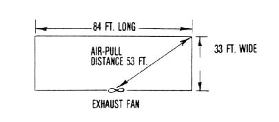
Design an exhaust annex pit ventilation system for a 33' x 84' total-slotted-floor building which is to house 30 gestation sows and 30 sows in farrowing (Figure 10).
1. From Table 1, the moisture and odor control ventilation rates per sow and litter are 10 and 35 cfm, respectively. The pit ventilation rates for farrowing, therefore, are:. 300 cfm for moisture control (10 cfm x 30 sows) and 1050 cfm for odor control (35 cfm x 30 sows).
2. Also from Table 1, the moisture and odor control rates per gestation sow are 6 and 20 cfm, respectively. This means pit ventilation rates for gestation will be: 180 cfm for moisture control (6 cfm x 30 sows) and 600 cfm for odor control (20 cfm x 30 sows).
3. Adding these farrowing and gestation figures, we find the total pit ventilation rates to be: 480 cfm for moisture control (300 + 180) and 1650 cfm for odor control (1050 + 600).
4.0If a single annex is to be located in the center of the downwind (in winter) sidewall, the maximum air-pull will be ((84/2)2 + 332)1/2 or 53.4 feet, which is close enough to the 50-foot limitation on distance of air-pull (Figure 11.).
5. Table 4 shows that the slot opening from pit into annex necessary to handle a maximum pit ventilation rate of 1650 cfm should be about 324 square inches. Suggested opening size to accommodate this rate is 8" x 42".
6. The fan or fans to be used must provide capacities of 480 and 1650 cfm. After selecting fans which provide these rates, use Table 5 to design the fan housing.
Pit ventilation is beneficial in all mechanically-ventilated slotted-floor buildings, even if manure is removed frequently to an outside manure storage. A properly-designed system improves the environment inside the building by removing odors, drying the slotted floor area and providing a gentle flow of warm, fresh air over the animals.
Both the exhaust duct and exhaust annex systems work satisfactorily, although the duct system gives somewhat better results. Either system can be designed and operated to minimize energy use.
Single copies of the following `Energy Management in Agriculture' publications are available free to Indiana residents from their county Cooperative Extension Service office or by writing to Media Distribution Center, 301 South Second Street, Lafayette, IN 47901-1232:
"Environmental Control for Livestock Housing" (AE-96)
"Insulating Livestock and Other Farm Buildings" (AE-95)
"Natural Ventilation for Livestock Housing" (AE-97)
"Solar Heating for Livestock Buildings" (AE-99)
"Troubleshooting Mechanical Ventilation Systems" (AE-100)
"Wind and Snow Control for the Farmstead" (AE-102)
New 4/80
Cooperative Extension work in Agriculture and Home Economics, state of Indiana, Purdue University, and U.S. Department of Agriculture cooperating; HA. Wadsworth, Director, West Lafayette. IN. Issued in furtherance of the acts of May 8 and June 30, 1914. Purdue University Cooperative Extension Service is an equal opportunity/equal access institution