A mechanically-ventilated confinement livestock building must have properly-sized fans, furnaces and slot air inlets it it is to operate satisfactorily. This worksheet was developed to help producers and builders calculate the capacities and dimensions of equipment needed tor specific livestock buildings. It should be used in conjunction with Purdue Extension Publication AE-96, "Environmental Control tor Confinement Livestock Housing," which deals with the principles and design of commonly-used environmental control systems.
This worksheet leads you through a step-by-step procedure for calculating the needs of an exhaust ventilation system, by tar the type most commonly used today. For design information on positive and combination positive/negative ventilations systems, consult publication AE-96.
An example situation is presented to illustrate the types of calculations involved and how they are `worked.' Be sure you understand where the various input figures come from, why they were used and how the answers were arrived at before applying the worksheet to your particular building. Some of the input data needed for the calculations are provided in Tables 1-4 which follow. At the end of the worksheet is a brief summary and information on sources of related publications and computer programs.
                                   Cold weather rates
			   --------------------------------------------
                          For moisture control on-
            		   -----------------------    Added for    For        Mild     Hot
Type of                    Fully   Partly    Solid   unvented      odor      weather weather
animal or facility         slotted  slotted  floor   heaters*      control    rates   rates
-------------------------------------------------------------------------------------------
                                         cubic feet per minute
Swine
Sow and litter               10      17        20       4           35         80     325
Pre-nursery pig (12-30 lb.)  1       1.6       2       0.5          3.5       10      25
Nursery pig (30-75 lb.)      1.5     2.5       3       0.5          5         15      35
Growing pig (75-150 lb.)     3.5     5.5       7       1.0         10         24      75
Finishing hog [150-220 lb.)  5       8        10       -           18         35     120
Gestation sow (325 lb.)      6      10        12       1.0         20         40     150
Boar (400 lb.)               7      12        14       2.8         24         50     180

Dairy
Cow                          16.5    28        33       -           50        130     600
Calf                          5       8.5      10       2           16         25     150
Milk rooms (total cfm)         -      -         8       -            -         25      50
Parlors (total cfm)            -      -         8       -            -         25     100
--------------------------------------------------------------------------------------------
* Increase the fully-slotted, partly-slotted and solid floor moisture
control rates by these amounts it unvented heaters are used
                                      Supplemental
                                         heat
				    ---------------
                            Inside  Slotted Solid
Animal unit                 temp.    floor  floor**
------------------------------------------------------
                                    BTU/hr.

Sow and litter               60 F        -   3500
                             70 F     3000
                             80 F     4000

Pre-nursery pig (12-30 lb.)  80 F      350      -

Nursery pig (30-75 lb.)      65 F        -    450
                             75 F      350
Growing pig (75-150 lb.)     60 F      600

Gestation sow and boar       60 F      500

Dairy calf                   70 F     1000   1000
------------------------------------------------------
* Sized for the odor control ventilation rate in a moderately
well-insulated building. Additional creep heat will be needed for
young animals in farrowing and nursery; size creep heaters at about
halt the space heat needs shown.

**  Solid floor scraped and bedded periodically.
                             Temperature
			  -----------------
Type of animal             Optimum   Range
----------------------------------------------
Swine
  Lactating sow             60 F   50- 70 F
  Litter, newborn           95 F   90-100 F
  Litter, 3 weeks           75 F   70- 80 F
  Pre-nursery pigs
    (12-30 lb.)             80 F   75- 85 F
  Nursery pigs (30-75 lb.)  75 F   70- 80 F
  Growing/finishing hogs    60 F   50- 70 F
  Gestation sow and boar    60 F   50- 70 F
Dairy
  Cows                      50 F   45- 70 F
  Calves                    70 F   45- 80 F
----------------------------------------------
Diameter               Speed   Capacity
in inches Horsepower   in rpm  in cfm*
------------------------------------------
Single- and multiple-speed fans

 7       1/20(2-speed) 1550       30
                       3000      150
 8       1/20(2-speed) 1550       80
                       3000      450
10       1/6(2-speed)  1550      375
                       3000      950
10       1/28          3000      600
------------------------------------------
12       1/6           1725     1000
14       1/4           1725     1600
16       1/4           1725     2400
------------------------------------------
18       1/4           1725     3000
20       1/3           1725     3200
24       1/2            770     5000
30       1/2            600     8000
136      3/4            545   11,000
48         1            525   18,000
------------------------------------------
                       Max.   Min.    Max.
 Variable speed fans   rpm    cfm    cfm

12       1/10          1700   250    850**
14       1/8           1750   110    1600
16       1/3           1725   850    2250
18       1/3           1600   500    3500
24       1/3           1050   800    4500
36       1/2            800   600    8000
------------------------------------------
*   All single-speed capacities shown are at 1/8 or 1/10 inch water
pressure.

** Maximum cfm is at 1/12 inch water pressure.
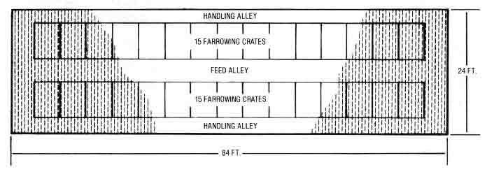
Example situation. Determine the heating and ventilation needs for environment control of a 24- by 84-foot, total-slotted floor farrowing house containing 30 sows and litters (Figure 1). Assume that the desired room temperature is to be 72 F, and that the building was properly constructed and insulated. (See AE-95, `Insulating Livestock and Other Farm Buildings," for recommended insulation levels in environmentally-controlled buildings.)
A. User's identification.
   1. Name:  William H. Jones
   2. Address:  Homestead Farms, Lafayette, IN
B. Building information
							               Our          Your
							              example      value

   1. Building size (width X length):				     24' x 84'   __________

   2. Type of livestock facility (farrowing, dairy freestall, etc.): Farrowing   __________

   3. Floor type (slotted, partly-slotted or solid):                 Slotted     __________

   4. Number of animals (count sow and litter as one):                 30        __________

   5. Type of space heating system (vented or unvented):             Unvented    __________
C.Recommended ventilation rates (from Table 1) and space heating rate (from Table 2) per animal unit.
Remember to increase the moisture control ventilation rate it an unvented heater is used. For example, from Table 1, each sow and litter on a total-slotted floor would require a moisture control rate of 10 cfm + 4 cfm = 14 cfm.
	                                                Our        Your
		                                      example      value
  1. Moisture control ventilation rate, cfm:            14       _________

  2. Odor control ventilation rate, cfm (optional):     35       _________

  3. Mild weather ventilation rate, cfm:                80       _________

  4. Hot weather ventilation rate, cfm:                325       _________

  5. Space heating rate, BTU/hr.:*                    3000       _________
* Size creep heat needs as indicated in AE-96. For purposes of this worksheet, creep heat is not considered part of the space heating system, but rather as a separate unit required for producing a microclimate for pig comfort.
D.Total recommended ventilation and heating rates.
Total requirement = rate per animal unit (Step C) X number of animal units (Step B.4). If two sizes of animals are housed, calculate the value required for the animals of each size, and combine to get the total quantity required.
  Our example
  1. Moisture control rate X No. of animals: 14  X  30 =    420 cfm

  2. Odor control rate X No. of animals:     35  X  30 =   1050 cfm

  3. Mild weather rate X No. of animals:     80  X  30 =   2400 cfm

  4. Hot weather rate X No. of animals:     325  X  30 =   9750 cfm

  5. Space heating rate X No. of animals:  3000  X  30 = 90,000 BTU/hr.

  Your values
  1. Moisture control rate x No. of animals: _________ x _________ = _________ cfm

  2. Odor control rate x No. of animals:     _________ x _________ = _________ cfm

  3. Mild weather rate X No. of animals:     _________ x _________ = _________ cfm

  4. Hot weather rate X No. of animals:      _________ x _________ = _________ cfm

  5. Space heating rate X No. of animals:    _________ x _________ = _________ BTU/hr.
E.Fan size selection (from Table 4 or obtain values from local fan dealers)
                                 (a)            (b)            (c)          (d)
                                            Additional                    Total fan
                                Total       cfm needed     Fan size for   capacity
                             recommended  (col.a - col.d   additional     (sum of
                             ventilation   from pre-       cfm needed     fan sizes
                            rate (Step D)    vious line)    (Table 4)     in col.c)
  Our example

  1. Moisture control:          420           -----          375/950        375-\ 2 sp

  2. Odor control (optional):  1050            675           375/950        950-/ fan

  3. Mild weather:             2400           1450            1600          2550

     (Additional fan):                       (____)          (_____)       (_____)

  4. Hot weather:              9750           7200            2400          4950

     (Additional fans):                      (4800)          (6000)        (9950)


  Your values

 1.  Moisture control:        _______       ________        ________      ________

 2.  Odor control (optional): _______       ________        ________      ________

 3.  Mild weather:            _______       ________        ________      ________

     (Additional fan):                      (_____)         (_____)        (_____)

 4.  Hot weather:             _______       ________        ________      ________

     (Additional fans):                     (_____)         (_____)        (_____)
F.Thermostat settings for furnace and fans.
Fans are those selected in Step E, col.c. Assume an on-off range of 5 F for furnace thermostat if actual range is unknown (see "Determining Fan Size and Thermostat Settings" in AE-96). Set mild and hot weather fans to come on in 2-4 F increments, starting about 3 F above the odor control fan setting (or furnace off-temperature if an odor control fan is not used).
1. Settings for furnace thermostat.
     a.Desired room temperature (see Table 3).

       Our example: 72  F

       Your value:_________ F

     b.Furnace on-temperature = Desired temperature (Step F.1.a) - 2 F.

       Our example:    72 F - 2 F = 70 F

       Your value:__________F - 2 F = __________F

     c.Furnace off-temperature = on-temperature (Step F.1.b) + on-off
       range (5 F if unknown).

       Our example:   70  F +  5 F  =  75 F

       Your value:________ F + ________ F = ________F
2. Setting for moisture control fan (from Step E.1 ,col.c) --should be operated continuously or off at 40F to prevent water pipe freezing.
     Our example: 375  cfm, off at 40 F

     Your value:       cfm, off at __________ F
3. Setting for optional odor control fan (from Step E.2, col.c) = furnace off-temperature (Step F.1.c) + 3 F (thermostat wired in parallel with switch or timer control to allow manual operation).
     Our example:  75 F + 3 F = 78; 1000 cfm, on at 78 F

     Your value:  ________ F + 3 F = ______; _________ cfm, on at _________ F
4. Settings for mild weather fans (from Step E.3, col.c)-see Step F instructions above.
     Our example:     1600 cfm, on at    81 F

                (________) cfm, on at _________ F)

     Your values:__________cfm, on at _________ F

                (_______)  cfm, on at _________ F)
5. Settings for hot weather fans (from Step E.4, col.c)-see Step F instructions above.
     Our example:  2400 cfm, on at 84 F

                (  5000 cfm, on at 87 F)

                (______)cfm, on at _________F)

     Your values:__________cfm, on at __________F

                (_______)cfm, on at _________F)

                (_______)cfm, on at _________F)
G.Slot air inlet length.
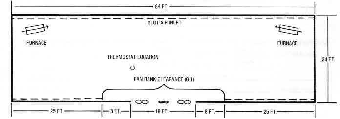
1.Fan bank clearance -i.e.,the wall length around the sidewall fans where no slot air inlets or soffit air intakes are located (Figure 2). If air inlet widths are adjusted with an automatic controller, fan bank clearances may not be necessary. In such cases, Step G.1=0.
Grouping fans in one location maximizes air inlet length for best air distribution. Locate fans so that air is not pulled more than 75 feet to prevent short circuiting (i.e., pulling stale exhausted air back into the building or exhausting incoming air before it has a chance to be evenly distributed around the room).
Fan bank clearance = the wall length occupied by the fans plus an additional 8-foot clearance on each side of the fan location. In new buildings, plan for a fan bank clearance of 16 feet for single-fan installations and (number of fans X 6-foot fan spacing) + 16 feet for multiple-fan installations. Only sidewall fans, usually for mild and hot weather, are used in calculating fan bank clearance. Pit fans are normally far enough below the slot air inlet to have no effect, unless an elevated exhaust is used.
The following calculations assume only one fan bank. If more than one fan location is used, simply sum the clearances for each fan location to determine total fan bank clearance.
  a. New system single wall fan clearance = 2 X 8 ft. on each side of fan = 16 ft.

  b. New system multiple installation fan bank clearance =
    (no. of fans X 6 ft.) + 16 ft.

     Our example:(3 fans  X 6 ft.) + 16 ft. = 34 ft.

     Your value:(___________ X 6 ft.) + 16 ft. = ___________ ft.

  c. Existing system fan bank clearance = fan bank length + 8
     ft. clearance on each side.

     Your value: __________ ft. + (8 ft. X 2) = __________ ft.
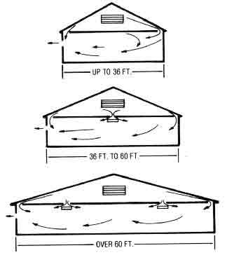
2.Total slot air inlet length and location (Figure 3).
  a. Inlet length for buildings up to 36 feet wide (inlets located
     along each sidewall) = [2 x building length (Step. B.1)] - fan bank
     clearance (Step G.1).

     Our example: (2 X 84 ft.) - 34 ft. =  134  ft.

    Your value: (2 x ___________ ft.) - ___________ ft. = ___________ ft.

  b.Inlet length for buildings 36-60 feet wide (double-sided center
    slot inlet system and slot inlets along each sidewall) = [4 X building
    length (Step B.1)] - fan bank clearance (Step G.1).

     Your value: (4 X ___________ ft.) - ___________ ft. = ___________ ft.

  c. Inlet length for buildings over 60 feet wide (two double-sided
     slot inlets evenly spaced across the ceiling and slot inlets along
     each sidewall) = [6 X building length (Step B.1)] - fan bank clearance
     (Step G.1).

     Your value: (6 X ___________ ft.) - ___________ ft. = ___________ ft.
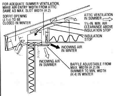
H. Width of slot air inlets (Figure 4).
1. Maximum ventilation rate per toot of inlet = total hot weather rate fan capacity (Step E.4, col.d) total slot length (Step G.2):
     Our example:   9950 cfm  /    134 ft. =  74.25 cfm/ft.

     Your value:  __________cfm /  _________ ft. = ___________ cfm/ft.
2. Maximum slot width = maximum ventilation rate per foot of inlet (Step H.1)/ 50 cfm/in. of slot width per foot of length (since 1 in. wide opening provides 50 cfm/ft. of length).
     Our example:    74.25  cfm/ft. / 50 cfm/in.-ft. =  1.5 in.

     Your value:  __________ cfm/ft. / 50 cfm/in.-ft. = _______ in.
3. Minimum ventilation rate per foot of inlet = moisture control rate fan capacity (Step E.1, col.d) / total slot length (Step G.2).
     Our example: 375 cfm /  134 ft. =  2.8   cfm/ft.

     Your value:  ________ cfm  /  _______ ft. = ________ cfm/ft.
4. Minimum slot width = minimum ventilation rate per foot of inlet (Step H.3) / 50 cfm/in. per foot of length.
      Our example:   2.8   cfm/ft. / 50 cfm/in.-ft. =   0.06 in.*    (use 1/8 in.)

      Your value:  __________ cfm/ft. /  50cfm/in.-ft. = __________ in.*
*An adjustable baffle is needed to close down the inlet to this width.
J. Attic and soffit air intakes (Figure 4).
Size on the basis of 2 cfm per square inch of free opening. Increase opening sizes accordingly it shutters or wire mesh screens are placed over the openings.
1. Soffit openings, sized for hot weather ventilation. Provide closures for cold weather ventilation. (Soffit openings are not needed in the fan bank clearance area).
     a.Soffit length = [2 X building length (Step B.1)] - fan bank clearance (Step G.1).

       Our example: (2 X  84 ft.) - 34  ft. = 134  ft. (X 12 in./ft. = 1608 in.)

       Your value:  (2 X _____ ft.) - _________ ft. = _________ ft. (X 12 in./ft. = _________ in.)

     b.Soffit area = total hot weather rate fan capacity (E.4, col.d) / 2
       cfm per square inch of opening (see Step J instructions).

       Our example: 9950  cfm /   2 cfm/sq.in. = 4975 sq.in.

       Your value:  __________ cfm /  2 cfm/sq.in. = __________ sq.in.

     c.Minimum width of soffit opening = soffit area (Step J.1.b) /
      soffit length (Step J.1.a).

       Our example:  4975 sq in. /  1608 in.=  3.09 in.

       Your value:   ________ sq in. / _________ in.= _________ in.
2. Total area of louvered openings in attic gables and ridge openings = mild weather rate fan capacity (Step E.3, col.d) / 2 cfm per square inch of opening.
     Our example: 2550 cfm   /   2 cfm/sq.in. =  1275  sq.in. (or about 9 sq ft.)

     Your value:  _________ cfm /  2 cfm/sq.in. = _________ sq.in.
Design of environmental control systems for livestock buildings is not an exact science. As pointed out in publication AE-96 and illustrated in this worksheet, the goal should be to obtain a system which will provide productive, efficient environmental conditions.
A livestock environment which is a degree or two from optimum won't make much difference in terms of animal performance. However, since energy use is directly related to design and operation of the environmental control system, livestock producers should try to estimate as nearly as possible and purchase properly sized equipment, then manage it efficiently to maintain the desired environment at a minimum expense.
Single copies of the following "Energy Management in Agriculture" publications are available free to Indiana residents from their county Cooperative Extension Service office or by writing to Media Distribution Center, 301 S. 2nd St., Lafayette, IN 47901-1232.
"Environmental Control for Livestock Housing" (AE-96)
"Insulation of Livestock & Other Farm Buildings" (AE-95)
"Methane Generation from Livestock Waste" (AE-105)
"Natural Ventilation for Livestock Housing" (AE-97)
"Pit Ventilation Systems for Livestock Housing" (AE-98)
"Planning Farm Shops for Work and Energy Efficiency" (AE-104)
"Solar Heating Systems for Livestock Buildings" (AE-99)
"Troubleshooting Mechanical Ventilation Systems" (AE-100)
"Wind and Snow Control for the Farmstead" (AE-102)
Also, a FACTS computer program, entitled Ventilation and Energy Needs Tabulation is available at county Extension offices which can be used to calculate ventilation needs in environmentally-controlled livestock buildings. Although the program does not provide as much specific design information as this worksheet, it does allow the user to experiment with the effects that various building temperatures, ventilation rates, animal densities and insulation levels would have on building heating costs.
New 9/80
Cooperative Extension work in Agriculture and Home Economics, state of Indiana, Purdue University, and U.S. Department of Agriculture cooperating; HA. Wadsworth, Director, West Lafayette. IN. Issued in furtherance of the acts of May 8 and June 30, 1914. Purdue University Cooperative Extension Service is an equal opportunity/equal access institution