AE-88
Solar Collectors
     Types of flat plate collectors

Collector Efficiency
     How can efficiency be improved?

What is a Solar Collector Made of?
     Cover materials
     Absorber plates
     Casing construction

How Much Solar Energy Is Available?

Solar Energy Storage
     Sensible beat storage
     Heat of fusion storage

Potential Applications

Space Heating

Solar Heating System

Designing a Solar Heating System
     Heating load
     Insulation level and beating requirements of a house

Sizing the Solar Heating System
     Collector area required
     Storage volume required
     Solar heat systems without storage
     Sizing the collector

What About Solar Heat for Livestock Housing?

Process Heat Applications

Grain Drying
     Sizing the collector

Hot Water Heating

Choosing a Heating or Drying System
There are many different approaches being taken today in the task of energy conservation. We are all becoming more aware of the limitations of the fossil fuels upon which we rely for much of our energy needs. In response to the "energy crunch", new sources have been investigated--nuclear, wind, geo-thermal, biofuels, and solar.
Of the total energy used in the United States, about 12% goes toward the heating of homes. On-farm uses in agriculture are about 3% of the total. Many different types of solar heating systems have been proposed to meet some of those needs. New companies are entering the market every year with a system to capture the "free" heat from the sun.
As homeowners, businessmen, and farmers it is to your advantage to understand how these systems work and how you might select one to meet your needs. A description of how solar heat is collected, how much is available, and how a system might be designed should help you in evaluating the use of energy from the sun.
There are two basic types of solar energy collectors used for the heating of air or water. They are the flat-plate type collector and the concentrating collector. (Figure 1). The concentrating collector focuses the direct rays of the sun which are incident on a reflector onto a smaller absorbing area, The flat plate collector involves no focusing of the radiation. It absorbs the direct rays and also is capable of absorbing diffuse radiation -- that is, the portion of the suns' energy which is filtered through clouds or is reflected from other objects. Because of the focusing effect, a concentrating collector can heat an absorber to a much higher temperature than can a flat plate collector. But, because of the use of only direct rays, the concentrating collector must continually "track" or "follow" the sun across the sky. The flat plate collector may remain stationary since it does not require direct radiation to operate.
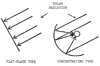
Flat-plate collectors are capable of providing the moderate temperatures required for space heating or cooling, up to about 250°F. They have the advantages of using both direct and diffuse solar radiation, no need for tracking the suns' path across the sky, and requiring less maintenance. They are mechanically simpler than the concentrating type. For these reasons, the flat plate collector is the logical choice for space heating needs.
There are many different designs of flat-plate collectors, but all have two basic characteristics in common. These are: (1) a plate to absorb the suns radiant energy, causing an increase in plate temperature, and (2) a circulating fluid, such as air or water, which picks up the heat absorbed by the plate and transfers it to a point of use or storage.
The two fluids most commonly used for absorbing and transferring the heat are air and water. An air collector can be as simple as a bare sheet of metal (as a metal roof), painted a dull black to absorb the most possible energy, with air blown underneath in a duct of some type as in Figure 2a.
A second type, called a cover-plate collector, (Figure 2b) uses a cover plate of glass, plastic or fiberglass with air circulated between the cover and the absorber plate. Heat loss from the absorber plate to the outside air (due to wind blowing across the surface and taking away some of the heat) is reduced by the cover, which acts as a barrier between the wind and absorber.
A third type, called a covered, suspended plate (Figure 2c) has air circulated both above and below the absorber plate. This provides twice as much surface area for heat transfer from the absorber plate to the air. The top cover reduces convection loss (loss from the wind across the surface), as in the covered plate type.
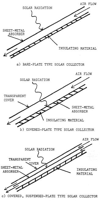
In most collectors, insulation for the back of the collector is necessary to reduce the conduction heat loss (heat loss through the rear of the collector). The covers of type b and c also reduce radiation heat loss from the front of the collector.
The same basic components of an air collector are present in a water collector--an absorber plate and a transfer fluid. The difference is in how the fluid is passed over the absorber.
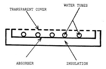
The basic water collector consists of an absorber plate, generally having water tubes attached, a cover, and insulation behind the absorber plate, as in Figure 3. Heat from the absorber plate is re-moved by the water circulating in the tubes.
Another type of water collector has no water tubes. The water simply flows down over the absorber in a sheet or in an open channel if the absorber is corrugated. The tube types are generally more efficient, but the open channel generally costs less. Freezing during periods of non-use in the wintertime is a problem when using a water type collector. To get around that problem, the collector must either be drained when not in use, or anti-freeze must be added to the water. Other problems with solar water heaters include leakage of the pipes and plumbing and corrosion of the metal. For these reasons, plus the fact that no heat exchanger is required for space heating, solar air heaters are the most common choice for livestock housing applications.
The efficiency of a solar collector is defined as the ratio of the amount of useful heat collected to the total amount of solar radiation striking the collector surface during any period of time.
                                     solar energy
                                      collected
Thus, collector efficiency = ------------------------
                                total solar striking
                                  collector surface
This ratio is multiplied by 100 to express as a percent efficiency. For example, if you receive 800 BTU/ft2 during a given day, then the percent efficiency is:
            400 BTU
	    ---------  x 100% = 50%
            800 BTU
Since "what goes in must come out", another way of looking at the concept of efficiency is to define it as the amount coming out that can be used to heat a house, barn, etc., divided by the total available.
The remainder of "what was available" comes out in losses. There are reflection losses from the cover, heat losses upward from the collector, and heat losses from the casing and piping around the collector. The more these losses can be reduced, the more useful heat from the collector, and the greater the efficiency.
The rate of flow of the air or water in the collector also affects efficiency. If the heat transfer fluid flows slowly, it becomes hotter because it stays in the collector longer. This causes it to lose more heat to the surroundings since there is a large difference in temperature between the fluid and its surroundings. If the fluid flows too rapidly, it may not have enough contact time to absorb enough heat to be useful or efficient. There is an optimum flow rate for every particular collector and application.
Some typical efficiencies for air heating collectors are given in Table 1.
          Type                   Efficiency
 ------------------------------------------------
    Plastic Tube Type                  25%
    Bare-Plate                         30%
    Covered Plate                      35%
    Covered, Suspended Plate           40%
    2-Cover, Suspended Plate           45%
 -----------------------------------------------
These efficiencies are day-long efficiencies -- that is, the percent of the total available for a day which could be collected by the different types on that day. Efficiencies for water type solar collectors are comparable.
There are several modifications of the basic collectors which will improve efficiency. If the collector is going to operate at more than 50°F difference between the outside air temperature and collector fluid temperature, efficiency may be increased by adding an additional cover. Each additional cover reduces the convection and radiation loss. But, in adding a cover, cost is increased and reflection losses from the glass or other material are increased. Again, an optimum number of covers must be found. For home applications, two covers appear best while for lower temperature requirements one cover is sufficient.
Selective absorbing surfaces are another possibility. The absorber is treated chemically so that it will absorb most of the radiation striking it but will not re-radiate very much of the absorbed heat out to the surroundings. This concept is somewhat analogous to a one-way glass or mirror, in which you can see through in one direction, but receive a reflected or mirror image from the other. This type of treatment is fairly expensive, but, especially for higher temperature applications, it increases the efficiency.
Reflectors can be used to increase the amount of radiation striking the collector face. Other modifications may be made including various more-efficient absorber plate designs -- overlapping glass, or corrugated, finned, or bonded tube-in-sheet design.
Improvements in efficiency must be weighed against the increase in cost and/or maintenance requirements of the system. Usually, the more efficient a collector is, the more costly it is. A less efficient, but also less costly collector may prove to be the more cost-effective in delivering a given amount of heat. As new design, manufacturing, and installation developments occur the relative cost effectiveness of alternate collectors will undoubtedly change.
Solar collectors are being constructed of many different materials and in a wide variety of designs. The materials used should be capable of turning weather as a roof or wall must, and withstanding the adverse effects of the suns' radiation. There should be a resistance to corrosion or clogging due to acidity, alkalinity, or hardness of water or the water-anti-freeze mixture, and freezing in the case of water collectors; depositing of dust and moisture in the case of air collectors, and breakage of the glazing (transparent cover) due to hail, thermal expansion, or other causes. The goal should be for a design that will give a useful and economical production of heat with a minimum of repair, maintenance, and component replacement.
Glass is used most often as a cover for solar collectors used for space heating of homes or for industrial or public building applications. It is a good transmitter of the incoming solar radiation, but transmits almost no radiant heat from the absorber surface to the surroundings. This is the so-called "greenhouse" effect, or "heat-trap" effect you may have heard about. This effect explains why the inside of your car gets hot on a warm summer day. The window glass traps the heat in the car. All of the heat is not trapped, though. The glass will absorb some of the radiated heat from the absorber, which will cause the glass temperature to rise, and some heat will be lost due to the temperature differential between the glass and surroundings. The glass reduces convection losses.
Either single strength or double strength window glass is commonly used. It has a transmissivity to solar radiation of 87%. This means that 87% of the incoming solar radiation can pass through the glass, the rest is either reflected or absorbed in the glass.
Where there is much danger of breakage from hail, or of vandalism, a one-half inch wire mesh has been used to protect the glass from damage. The screen shades the glass and decreases the effective collector area by about 15% so the total area must be increased accordingly. There is generally not a major problem with breakage, though, except when bail strikes the glass surface at right angles.
Plastic films or sheets are also used as cover materials. Only a few types now available cam withstand the suns' rays for more than one or two years. The transmissivity for solar radiation is 92%, but the plastics do not perform as well as a heat trap, allowing 30% of the long wave radiation to be radiated to the surroundings from the absorber. For lower temperature applications such as grain drying, or for temporary installations, though, the plastics do have certain advantages. They are flexible in withstanding wind loads, hail, etc., and are easier to install and cheaper than glass. They provide a convection barrier in the same way glass does. In some designs with two covers, one layer of glass is used along with a layer of plastic underneath.
Greenhouse grade fiberglass is most often used as a cover in livestock buildings. It performs in much the same fashion as glass except the transmissivity to solar radiation is somewhat less (approximately 80% vs. 87% for glass). Also it is more resistant to breakage from expansion or contraction of the casing.
Desirable characteristics of an absorber plate are (1) to absorb as much of the suns' radiant energy as possible, (2) to lose as little heat as possible to the surroundings, and (3) to transfer the heat retained to a fluid.
An absorber plate painted black will absorb more radiant energy than any other color of plate. A black surface has an absorbtivity for solar radiation of about 95%. A flat black paint should be used to reduce possible reflection.
To reduce the amount of heat radiated from the plate to the surroundings, selective coatings may be used. These coatings absorb the same amount of radiant energy as regular black surfaces, but emit, or radiate, much less.
For lower temperature applications such as grain drying or swimming pool heating, selective coatings are generally not economical. The temperature is low enough that losses due to radiation from the plate are small. For home heating, the use of a selective surface may eliminate the necessity of an additional cover plate to obtain increased efficiency from a given collector.
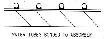
Materials generally used for collector plates are copper, aluminum, and steel. Copper is the most expensive, but also has the highest thermal conductivity. Steel is the least expensive and also has the lowest conductivity of the three. For water-heating collectors, especially, the conductivity is important. For copper, the water tubes (which are bonded to the absorber plate -- see Figure 4) may be spaced further apart than for a material of less conductivity. Another important consideration is the bond of the water tubes to the plate. The soldering connection must be good or efficiency will suffer. Such bonding presents more of a problem with aluminum. Some plates use bonded tube-in sheet design like many refrigerator shelves used to be (see Figure 5), which provides good thermal contact.
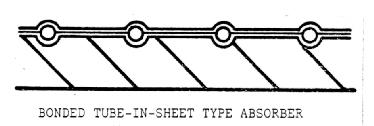
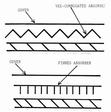
If the entire area of the absorber is swept by the transfer fluid, the conductivity of the plate is much less important. For air collectors, wood and plastics have also been used as absorber plates. They generally do not perform quite as efficiently as the metals but are sometimes acceptable since the cost per ft2 of collector might be reduced. Surface area of the plate also affects heat transfer in air collectors. Many designs include fins or corrugations to increase this area, thereby increasing heat transfer (see Figure 6).
The casing may be a wooden, sheet-metal, or fiber reinforced plastic frame. For the wood frame, the backing should be moisture resistant. Sheet metal frames should be painted to resist rusting.
The cover glass should be secured firmly with weather resistant gaskets which allow for the expansion and contraction of the glass, while keeping moisture out. This expansion/contraction joint is very important, since glass has a coefficient of expansion one and one-half times greater than steel and two tines greater than wood. This joint is not nearly as important for plastic or fiberglass covers. Insulation should be added to the back and exposed sides of the collector to reduce heat loss in that direction.
The amount of sunlight striking the outer layer of the earth's atmosphere changes very little through-out the year. As it travels through the atmosphere to the earth's surface, the sunlight is scattered and absorbed by dust, water vapor (clouds), gas molecules, and air pollutants. Only a fraction of the direct rays from the sun eventually strike the ground. Because atmospheric conditions change from day to day, the amount of solar energy received varies also.
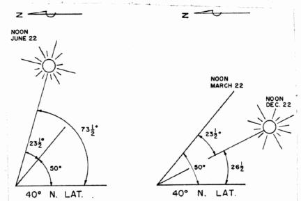
The season of the year also determines how much solar radiation reaches the earth. As shown in Figure 7, rays of sunlight strike the northern hemisphere more directly in the summer, causing more heating and higher temperatures. The less direct solar radiation in the winter months must also pass through more of the atmosphere, which further scatters and decreases the amount striking the ground. The scattered radiation that eventually does reach the earth along with the direct sunlight is called diffuse radiation.
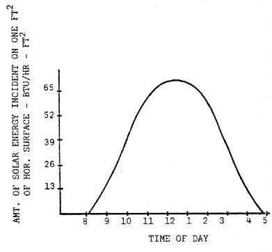
Incoming solar energy also fluctuates on an hour to hour basis. During the winter, the majority of solar energy is received from about 9:00 in the morning until about 3:30 in the afternoon. Within this time period, the rate increases to a high value at noon and then decreases again. This is shown graphically in Figure 8.
Records of actual solar radiation are not as numerous as those for rainfall and temperature. Most weather stations which do measure solar radiation record it as the total amount falling on a horizontal surface.
Table 2 summarizes fifteen years of data accumulated at Indianapolis, Indiana for the period 1951-1966. The values are expressed as BTU per sq. ft. per day and are the average of all days within a month. The high and low measured radiation values are the highest and lowest monthly readings records in a 25 year period. The percent transmission figure reflects the relative number of clear days. Also shown are the average values which might be expected on various south-facing tilted surfaces.
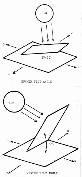
The greatest amount of solar energy will be received if the collector is faced to the south, due to the location of the sun in the sky. To receive the maximum amount of solar radiation upon a surface during an Indiana winter, it should be tilted at an angle of 55-60° from the horizontal. In summer, the maximum amount of solar radiation strikes the collector tilted at an angle of 25-30° from horizontal (Figure 9). If the surface does not face due south the greatest amount of collection will occur in either the morning or afternoon instead of at solar noon. This will decrease the daily total of collected energy.
                                                           Average Quantity of Radiation Incident on a South
           Extra-          Measured2        Ave. Per-3     Facing Surface at Tilt Given
Month    terrestrial1  High   Ave    Low    Cent Trans.     18.4° (4/12 roof)  30°     60°      90°(vertical)
------------------------------------------------------------------------------------------------------------
JAN         1415       851    610    402       43%             909            1049   1220    1115
FEB         1870      1183    845    660       45             1115            1234   1317    1109
MAR         2540      1397   1155    822       45             1363            1420   1374    1007
APR         3165      1758   1540    575       49             1632            1632   1364     758
MAY         3585      2263   1890   1433       53             1878            1796   1390     662
JUN         3750      2325   2080   1780       56             2026            1914   1413     577
JUL         3645      2229   2025   1644       56             2013            1923   1488     698
AUG         3300      1935   1840   1492       56             1950            1950   1630     905
SEPT        2760      1820   1550   1286       56             1828            1966   1844    1351
OCT         2100      1363   1120    884       53             1478            1635   1747    1469
NOV         1345       870    680    369       44             1012            1170   1360    1241
DEC         1270       770    510    361       40              816             959   1148    1087
------------------------------------------------------------------------------------------------------------

1. Extraterrestrial radiation is defined as that expected if
atmosphere were perfectly transparent.  For a given location, it is
dependent only upon time of year.

2. Baker, D. G. and D. A. Haines.  1969.  Solar Radiation and Sunshine
Relationships.  North Central Regional Research Publication No. 195,
University of Minnesota Agricultural Experiment Station, St. Paul,
Minn.

3. This is the average percent of the extraterrestrial radiation that
reaches the earth's surface.
If you know the efficiency for a given collector, then you can calculate the average amount of heat you will receive per day in a given month. For example, suppose you live in Indianapolis and have a collector with an efficiency of 50%. Assume you would like to know the amount of energy you will collect on an average day in December with your collector mounted on the roof at a slope of 30°. You would read from table 2 a value of 959 BTU per day. You would collect 0.5 x 959 BTU/day = 480 BTU/day on the average for December for each square foot of collector area.
For about 50% of the hours of the year, any location is in darkness. A solar heating system must be designed so that it will provide heat when needed. The alternatives are to (1) use a storage system which will retain the energy collected during the day to be used at night, (2) use other means of heating during off-periods, or (3) choose operations which need only operate when the sun shines, such as heating a shop which is used only during the day. To use solar energy for nighttime or during cloudy periods, a heat storage system must be used. One possible system is sensible heat storage, which is the retaining of heat by a material, as when a rock is heated, it will remain hot for awhile. The other type is heat of fusion, or latent heat, storage which involves the freezing or thawing of a substance.
Sensible heat storage is the most widely used system at the present time. Sensible heat storage involves the storing of heat in a substance by the virtue of a change in temperature. The two systems commonly used for this method are tanks of water and beds of rocks.
Water is an inexpensive and readily available material for storage systems. The specific heat of water is 1.0 BTU/°F-lb, which means that 1 BTU of heat will raise the temperature of a pound of water one degree in temperature. One cubic foot of water weighs 62.4 lb., so a single cubic foot will store 624 BTU if its temperature is raised 10°F.
On a larger scale, a 1500 gallon storage tank would contain over 6 tons of water (12,513 lb.). With a temperature rise of 50°F. the tank would have a storage capacity of 625,650 BTU. With this kind of temperature differential, it is important to have good insulation around the storage tanks. A pump must be used to transfer the water from tank to collector and gravity will return the water. If anti-freeze is used, a heat exchanger must be installed. Otherwise, 1500 gallons of anti-freeze/water mixture would be required, which would be very expensive. A heat exchanger is a system of toils which is placed in the tank and connected to the collectors. The hot water/anti-freeze mixture heats the coils which in turn heat the water in the tank. For retrieving the heat from storage, the hot water rises to the top of the tank because it is less dense than the cooler water and can be tapped off there. It is then either circulated through the house or run through a heat exchanger to heat air for the residence.
For air collectors, rock is generally used as the storage material. The specific heat of rock is about 0.20 BTU/lb degree F., and a cubic foot of solid rock weighs 140 lb., so one cubic foot of solid rock will store 280 BTU if it's temperature is raised 10 degrees F. It has been found that a bed of 3/4 inch - 3 inch rock works best in a storage system. The diameters should be approximately equal to provide the largest amount of void, or empty space between the rocks. This allows air to flow through and come in contact with a large amount of surface area to heat the rocks. Also the rocks should have a smooth surface to decrease air friction. The void space in a rock bed of this type is about 1/3 of the total volume, so one cubic foot of storage weighs about 105 lb. To obtain the same amount of storage as a 1500 gallon water tank, you would need about 625 cubic feet of rocks. Research is now being dome on other possible sensible heat storage methods including concrete blocks and earth.
Heat of fusion storage involves the freezing or thawing of a substance. Certain salts have a heat of fusion of 90 to 118 BTU/lb at a certain temperature. For example, for Glaubers salt (Na2SO4 10 H20) it takes 108 BTU to melt one pound at 91 degrees F. When the salt solidifies, it releases this heat. The high heat absorbing capacity of this material reduces the storage size required substantially. Equivalent salt storage is about one-fourth the size of water storage and about one-twelfth the size of rock storage.
There are problems, though. The salts are expensive materials and have exhibited some tendencies to deteriorate, which then requires replacement after a time. Researchers are working on these problems and an acceptable salt storage system may go on the market soon. Table 3 compares the different storage methods.
              BTU/lb    BTU/ft3   BTU/gal
--------------------------------------------
 Water          50      3,120       417

 Rocks        10.5      1,050       ---

 Salts         125     12,500       ---
-------------------------------------------
1. For a 50°F temperature rise; Rock 100 lb/ft3
including void space, salts 100 lb/ft3, water 62.4 lb per
ft3
The potential applications for the flat-plate type solar collector vary from hot water heating and swimming pool heating, to grain drying and the heating of livestock buildings, to heating and cooling of residences. There are many different approaches to using solar energy in each of these areas.
Space heating with solar energy involves utilizing the heat obtained from a solar collector to increase the temperature of an area to an acceptable or comfortable level.
This area might be a room, house, machine shop, garage, or livestock barn. A solar collector might provide all of the heat needed, or only a fraction of the requirements.
There are many different types and combinations of solar collectors, storage, and transfer fluids that could be used. We will look at the design of a heating system for a home using air as the transfer fluid and rocks as storage. Then we will design a system for the same home with no storage. Finally, we will extend the design principles used for a home to livestock housing.
The components of a solar house heating system are a collector storage system, and a means of circulating the heat transfer fluid (air or water). In addition to the above components, a conventional backup system must be included to meet the heating requirements during the extended periods of cloudiness or extreme cold. To provide the storage volume which would be necessary in order to rely on solar heating alone here in Indiana is neither economical or practical. The volume would be extremely large. A more reasonable size to consider is three to five days storage of heat.
The percentage of the heating requirements supplied by solar heat varies with different installations. In general for climates comparable to Indiana, solar systems have been designed to supply between twenty-five and eighty-five percent of the total needs. The decision as to what percentage to supply with solar heat depends on the relative costs of fuel, solar equipment, and insulation.
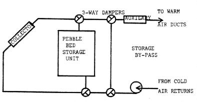
A diagram of a solar heating system with storage is shown in Figure 10. The path that air takes through the system is controlled by dampers. When the sun is shining air is blown through the collector and the heated air from the collector warms the home. At nighttime or on cloudy days the air is not directed through the collector but passes instead through the storage unit, which warms the air to heat the house. The auxiliary heating unit is fired by conventional fuel and adds heat to the air if the air from the collector or storage is not warm enough. When too much solar heat is being collected and, the house doesn't need heat, the air from the collector is blown through the rock storage and back to the collector. The stored heat may then be used later to warm the home.
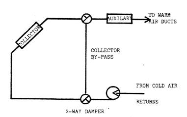
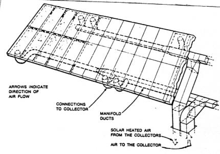
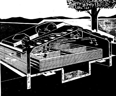
A system which does not include storage is shown in Figure 11. In this system air is blown through the collector and warms the home as before when the sun is shining. When no solar heat can be collected the collector is bypassed and the auxiliary unit takes over. Since there is no storage in this system, solar heat can only be used during the day when it is available, and any excess collected cannot be used. Figure 12 shows how an air type collector might be installed on a roof.
In designing a solar heating system, there are several things which need to be considered. The availability of the solar energy, which we have already discussed, is, of course, a prime consideration. The heating load for the location is also important.
In the actual system itself, the extent to which the structure is insulated, the efficiency of the collector, and the collector area and storage volume should all be considered in designing your heating unit.
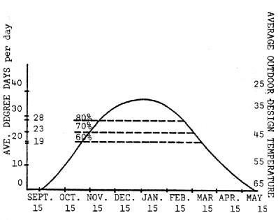
The heating load varies according to the part of the country you are in. The size of the load is measured in units called degree days. A degree day is defined as the difference between the inside design temperature and the average outside temperature for a particular day (24 hours). For example, if the average temperature on December 21 is 30°F, then the number of degree days on December 21 is 65 - 30 - 35 degree days. The inside design temperature is generally taken to be 65°F in determining the number of degree days of heating load for home heating. The total degree days for a year give an indication of the heating load over an average heating season.
In Indiana, the average number of heating degree days is about 5500 at Indianapolis. Figure 13 shows how the number of degree days per day varies through the heating season. The area under this curve is the total for the season.
The heating requirements of a house depend upon how well the ceiling, walls, windows, etc. can resist the outward flow of heat and upon the inside temperature which is desired.
The ability of a building material to resist this heat flow is referred to as the "R" value of the material. The R value may be given per inch thickness of material or as a value for the total thickness. Some R values for typical building materials and components are listed in Table 4.
                                                     Insulation Value2
                                                 Per inch          For thickness
Material                                         thickness            listed
-----------------------------------------------------------------------------------
1.  Batt or blanket insulation
    Glass wool, mineral wool
    or fiberglass                                3.70

2.  Fill type insulation
    Glass or mineral wool                        3.00-3.50
    Vermiculite (expanded)                       2.31-2.27
    Shavings or sawdust                          2.22
    Paper or wood pulp                           3.70

3.  Rigid insulation
    Wood fiber sheathing                         2.27-2.63
    Expanded polystyrene, extruded               4.5
    Expanded polystyrene, molded                 3.57
    Expanded polyurethane (aged)                 6.25
    Glass fiber                                  4.00

4.  Ordinary building materials
    Concrete, poured                             0.08
    Plywood 3/8"                                 1.25                 0.47
    Plywood 1/2"                                 1.25                 0.63
    Hardboard 1/4"                               1.00 to 1.37
    Cement asbestos board, 1/8"                                       0.03
    Wood leveled siding 1/2" x 8"                                     0.81
    Aluminum siding                                                   0.61
    Insulating board sheating 1/2"                                    1.32
    Plaster                                                           0.32
    Asphalt shingles                                                  0.44
    Wood shingles                                                     0.94

5.  Window glass, includes surface conditions
    Single-glazed                                                     0.89
    Single-glazed & Storm windows                                     1.79
    Double-pane insulating glass                                      1.45-1.73

6.  Floor Perimeter
    Concrete, w/o perimeter insulation                                1.23
    Concrete, with 2" x 24" perimeter insul.                          2.22

7.  Air space (3/4" or larger)                                        0.90

8.  Surface conditions
    Inside surface                                                    0.68
    Outside surface (15 mph wind)                                     0.17
----------------------------------------------------------------------------------------
1 From ASHRAE Handbook of Fundamentals, 1972.          2 Mean temperature of 76°F
In finding the heating requirements of a home, the R values for the components must be found, then the heat loss can be determined. Assume the house is constructed as in Figure 14. The R values would be determined as follows, using figures from Table 4.
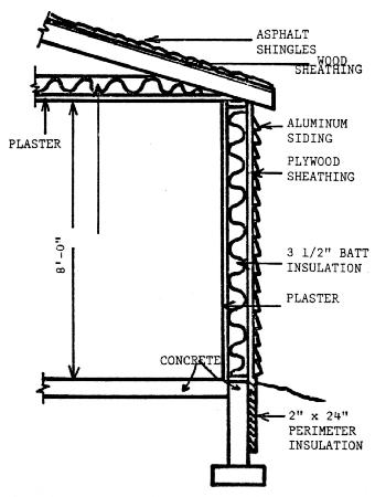
 1. Windows - Single glass + storm windows        R=1.79

 2. Wall  - 3 1/2" batt insulation 3 1/2 x 3.70    12.95
            Plywood sheathing                       0.47
            Aluminum siding                         0.61
            Plaster                                 0.32
            Inside surface                          0.68
            Outside surface                         0.17
            Total R                                 15.2

 3. Ceiling - Asphalt shingles
              Wood sheating                         3.63
              Vented Attice space
              Plaster                               0.32
              3 1/2" batt insulation               12.95
              Outside surface                       0.17
              Inside surface                        0.68
              Total R                              17.75

 4.  Perimeter - Concrete, 2 x 24" insulation R=2.22
Now that you know the R values for your house, you can determine how much heat it will lose. First, the window, wall, and ceiling areas and the perimeter must be determined. The R values are then used to determine how much heat is lost per degree day. The larger R value, the less heat will be lost. The heat loss per day is calculated as follows:
Step 1 Determine areas, perimeter, and volume
 (a)   Perimeter   = 2 x (length + width)
                   = 2 x (30' + 65')
                   = 190'
 (b)  Window area  = 200 ft2

 (c)  Door area    = neglect

 (d)  Wall area    = (Perimeter) x (ceiling ht.) -
                     (window area)
                   = (190) x (8) - 200
                   = 1320 ft
 (e)  Ceiling area = length x width
                   = (65) x (30)
                   = 1950

 (f)  House volume = 1950 x 8
                   = 15,600 ft3
Step 2 Determining heat loss/degree day
		          Area
     Heat loss/deg day = ----- x 24 hr/day =
                           R

(a) Windows    = 200  x 24 = 2681 BTU/deg day
		------
                 1.79


(b) Wall       = 1320 x 24 = 2084 BTU/deg day
		-----
                 15.2


(c) Ceiling    = 1950  x 24 = 2636 BTU/deg day
	         -----
                 17.75


(d) Perimeter  =  190  x 24 = 2054 BTU/deg day
		------
                 2.22

(e) Infiltration loss = (0.75) x (.018) x (volume) x 24
                      = (O.75)(.018) x (15,600) x 24
                      = 5054 BTU/deg day

(f) Total Heat loss/deg day = 14,509 BTU/deg day
Now that you have determined the heat loss for your home, you can proceed to size the solar heating system. First, we will consider a system with heat storage, then we will look at a system without any form of storage and compare the designs.
Assume that we would like to obtain 80% of the required heat from solar energy. Also assume that the solar collector has an overall efficiency of 45%. The total heating load of the season is 5560 degree days for Indianapolis. Eighty percent of this is 4450 degree days. To provide this amount of heat the solar system will need to provide all of the heating requirements below the 80% line in Figure 13. This can be done by designing the system for an outside temperature of 37°F, which coincides with the 80% line at a heat load of 28 degree days per day. The collector and storage would be sized as follows:
A. Collector Area Required
    Step 1  Total Heat Required - BTU's/day
         Previously, we found a heat loss of 14,509
         BTU/degree day

         Total heat loss = 14,509 BTU x 28 deg days
                         = 406,252 BTU/day

    Step 2  Heat Collected Per Ft2 of Collector
         Assume we will mount the collector on the
    roof.  The tilt angle on a 4/12 roof slope is
    18.40°  From Table 2, we find we will receive
    816 BTU/ft2 in December
         Amount Collectable = (collector efficiency)
                              x (BTU/ft2-day)
                            = 0.45 x 816 BTU/ft2-day
                            = 367 BTU/ft2-day

     Step 3  Collector Area Required
         The collector area required
              (total heat required)
            = ----------------------
              (heat from collector)

              406252 BTU/day
	    = --------------
              367 BTU/ft2-day

            = 1107 ft2
B. Storage Volume Required
Assume we would like to have three days storage. This will allow our system to provide heat over a three day cloudy period. In a winter with many cloudy stretches, we may not provide the 80% heating hoped for due to a lack of storage. On the other hand, we are limited by space and cost of the storage. If the calculations we perform indicate a relatively small storage volume required for three days, we may decide to increase the volume to handle more days storage to add flexibility to the system.
Step 1  Amount of heat storage needed (BTU's)
     Amount needed = (number of days storage) x
                     (heating requirements BTU/day)
                   = 3 x 406,252
                   = 1,218,756 BTU

Step 2  Volume of rocks required

     Volume              (BTU's storage)
            =  ---------------------------------
               (Storage capacity (BTU/ft3), Table)

                1,218,756 BTU
            = -----------------
                1050 BTU/ft3

            = 1160 ft3
The weight of rocks is 105 lb/ft3, so the total weight of this amount of storage would be:
		   lb      1 ton
   1160 ft3 x 105 ---- x  ------- = 60.9 tons
                   ft3    2000 lb
The collector area required may seem large and, indeed, it is. It would more than cover the south roof of your home. To reduce the size of your collector, several things could be done. If the tilt was increased to 600 from horizontal, then less area would be required since more BTU's would be received per square foot of surface. If more insulation were added to the ceiling, for example, the losses would be reduced and less heat would be required. This would also allow you to reduce the area. The economics of using more insulation verses additional collector area should be checked when installing a solar unit. The final alternative is to settle for a lessor percentage of the total to be supplied with solar energy.
If no storage is used in the heating system the flexibility of the system is reduced. Heat from the sun may be used only during the day for the period of time in which the sun shines. None can be used at night or on cloudy days. Any excess heat which is collected must be discarded.
Since no energy can be stored, the size of the collector required must be calculated in a different way. The average amount of solar energy received on a horizontal surface was shown to vary during a typical day in December as in Figure 8. A reasonable goal for heating directly from the collector would be to provide the total heat required from 10:00 in the morning until 3:00 in the afternoon. As you can see from Figure 8, the energy received is much greater around noon than at 10:00, but the value per hour to use in determining the availability would be the 10:00 value. By using this value you will be assured of receiving at least that amount from 10:00 until 3:00 on a typical day. The amount received on a tilted surface could be found by multiplying this value by the appropriate factor from Table 5.
                       Tilt factor for tilt angle of:
		       ---------------------------------
  MONTH                0°          18.4°        30°       60°       90°
-----------------------------------------------------------------------
  Jan. or Nov.          1           1.49       1.72      2.0      1.83

  Feb. or Oct.          1           1.32       1.46      1.56     1.31

  March or Sept.        1           1.18       1.23      1.19     0.87

  April or Aug.         1           1.06       1.06      0.89     0.49

  May or July           1           0.99       0.95      0.74     0.35

  June                  1           0.97       0.92      0.68     0.28

  Dec.                  1           1.60       1.88      2.25     2.13
-----------------------------------------------------------------------
In designing the system the average temperature for the day, not including night-time temperatures, should be used. At Indianapolis this temperature is 33°F in December. The number of degree days for this typical day would be 65°-33° = 33 degree days.
Step 1 Determine Heat Loss Per Hour
  Previously, we found a heat loss of 14,509 BTU/deg day

  Heat Loss per hour = (heat loss/deg day) x (# of deg days)
                       --------------------------------------
                                   24 hr./day

                     = (14,509) x (32)
                       ----------------
                               24

                     = 19,345 BTU/hr
Step 2 Determine Amount of Solar Heat Collectable at 10:00
    Amt. Collectable =  (Collector Efficiency) x
                        (Tilt Factor from Table) x
                        (Solar Radiation on a horizontal
                        surface at 10:00
                        BTU/hr)
                     =  (0.45) x 1.6) x (39)
                     = 28 BTU/ft2-hr

Step 3  Determine Collector Size

    Collector size = (heat loss/hr)
		     ------------------
                     (Amt Collectable)

                   = 19.345
		     --------
                       28

                   = 690 ft2
From these calculations we have found that 690 ft2 of collector area will warm your house on an average day in December from 10:00 until 3:00. This is 5 hours, or 20.8% of the day. If every day were an average day, then, you would save 20.8% of your beating bill. But, since there are many days which will not have as much energy available, a more realistic expectation is 10-15% of your total heating requirements. On many days you would need to mix cooler outside air with the heated air from the collector since you night receive more heat than necessary during that time period. This points up the value of a storage system to save the extra heat which is otherwise not used.
For a machine shed, shop or other building which is only occupied during the day, a collector without storage becomes more practical. No heat is required at night and the temperatures in the area can be lowered to 50-55° for a working atmosphere. The heat losses are calculated in the same way as before. The number of degree days may be reduced since the inside temperature is 50-55° instead of 65°F. On this type of system a small auxiliary heater might be used along with the solar system. It could then take over whenever a below average day for radiation occurred.
Farrowing houses, calf barns, poultry houses, and finishing barns have been heated with solar energy. Both covered-plate and bare-plate types of collectors have been used to heat the air for ventilation of these buildings. The bare plate type generally consists of a metal roof painted black over en air duct. The covered plate type uses fiberglass or plastic as the cover plate.
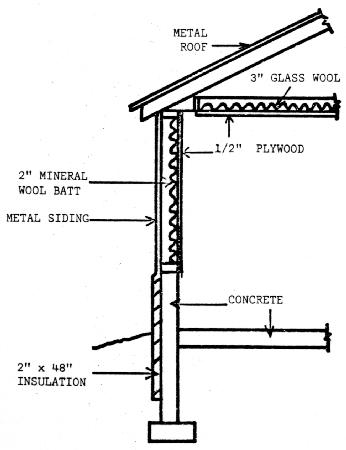
The procedure for designing a solar heating system for a livestock building is quite similar to that for a solar home. The heat losses are calculated in much the same way with only a few exceptions. The inside design temperature is generally lower. In a farrowing house with radiant heaters for the small pigs, the temperature is approximately 60°F. Table 6 shows some common inside design temperatures. In livestock buildings, a heat loss component is figured for ventilation rather than by the infiltration method used for homes. Table 6 lists common air change rates for winter. The heat production of the animals must also be considered, since a significant amount of heat is produced by them. The heat losses for the farrowing house described in Figure 15 would be calculated as follows:
Step 1 Determine all BASIC INFORMATION
                                           R values
Ceiling area         -      1536  ft2       12.58
Wall area            -      1056  ft2        9.61
Fdn. Wall            -       352  ft2        8.50
Perimeter            -       176  ft         2.22
Building volume      -    12,288  ft3

Step 2 Determine heat loss for 1 degree day

     This calculation is the same as for the home
heating example, except for the ventilation calculation.

                          Area
Heat loss/degree day =    ----  x 24
			   R
Ventilation loss     =  (.018) (24) (Air changes/hr) (volume)

                     = 15,925 BTU/deg day
The total heat loss/degree day is determined as before by adding up the component losses.
Step 3 Heat produced by stock
    Heat produced =  (Qs, from table) x (# of animals) x (cut/animal) x 24
                  = (320 BTU/hr-cut) x (20 sows & litters) x (3) x 24
                  = 460,800 BTU/day
                  Air Exchange Rate     Heat Production     Ins. Des. Temp.
                     (changes/hr)         (BTU/hr-cwt)           (°F)
------------------------------------------------------------------------------------
Hogs                     3                    293               55-60

Poultry           30 ft3/hr-bird        31.2 BTU/hr-bird         55

Dairy                    6                    230                50

Sow & Litter           2-3                    320                60
Having calculated the heat losses per degree day you would size the collector and storage components of your system the same way they were calculated for a house. Find the number of degree days/day for the percentage level of solar heat you wish to supply. Them calculate the total heat losses for a day, remembering to subtract from these losses the amount of heat supplied by the stock in a day. Using the adjusted loss figure you can then calculate your component sizes.
Figure 16 shows a typical layout of a solar heating system which uses concrete block as the storage material. In this design, the block has been added as a false wall on the outside of the existing wall. A rock bed storage could also be used as in the house example.
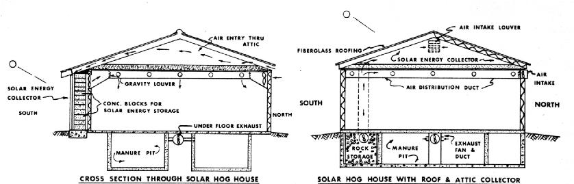
Of course, a system may be designed without storage. In such a system the losses per hour would be found for the daytime temperature as before and the heat produced by the stock (BTU/hr) would be subtracted from this. The sizing procedure would be the same as in the house example. Again, 10 to 15% of the heat requirements with an absolute maximum of 20% is about all you can expect to provide without storage. One such system is shown in Figure 17. Air is pulled in at the gable ends of the roof and is warmed by solar energy as it passes through the collector ducts. The warm air is pulled to a central distribution duct by fans and forced down into the building. It is exhausted through gravity type shutters in the sidewalls. A supplemental heating system is used at might and during cloudy periods. For summer ventilation, the air flow is reversed and blown out through the roof in this design. Besides the heat from the sun, the air "picks up" some of the heat escaping from the ceiling, thereby recovering heat which would otherwise be lost.
Besides space heating, solar energy can be used in some types of process heating situations. This involves utilizing the heat obtained from a solar collector to heat or pre-heat a fluid (air or water) for the use in some process--grain drying, hot water heating, or industrial drying, for example.
One application of solar energy in process heating is that of grain drying. There has been a significant amount of research done in recent years to determine the best methods. Heat from bare or covered-plate collectors on the roof of nearby buildings has been studied, also the use of free-standing collectors of both the flat-plate type and the plastic tube type (Figure 18). All of these applications have been related to low-temperature in-bin drying systems. The temperatures required for high speed drying methods make solar drying with flat plate type collectors impractical. Sophisticated concentrating type collectors could provide the necessary temperatures, but would be much to expensive at the present time.
For drying shelled corn, a collector which will heat the incoming air to 20°F at noon on a clear day is about right to produce 13% moisture corn. This would be for a "solar-only" operation with possibly a standby electric heater for long cloudy or rainy periods. If the collector is used mainly to supplement an electric heater them about a 10°F temperature rise is sufficient.
Assume we have a 2,000 bu. bin filled with corn and our drying system requires a 2.5 cfm/bu air flow rate. Also assume that we will be drying in October and would like to supplement in electric heater with solar heat from a plastic tube type collector. The procedure for sizing the collector would be as follows:
Step 1 Amount of heat needed
     Amt. needed = (CFM) x (TEMP. RISE) x 1.1
                 = (2.5) x (10) x (1.1)
                 = 25 BTU/hr-bu
Step 2 Amount of heat available/ft2
Table 7 shows that for October on a clear day at noon we would receive 208 Bu/bu-ft2.
     Amt collectable = (Amt received) x (Collector efficiency) x (Tilt factor)
                     = (208) x (.25) x (1)
                     = 52 BTU/hr-ft2
-------------------------------------------
         September                   249

         October                     208

         November                    163

         December                    143
------------------------------------------
Step 3 Collector Area Required
    Area =   (Heat needed)
           ----------------  x (# of bu)
           (Heat collected)

         =  25 BTU/hr-bu
           --------------- x (2000 bu)
            52 BTU/hr-ft2

         =  962 ft2
If the bin wall or a wall or roof of a machine shed were used as the collector surface them the amount available would need to he modified by the appropriate factor from Table 5.
Hot water for home use or for swimming pool heating can be obtained from solar energy systems. One system involves the use of a conventional water collector with a pump to circulate the water to he heated. Another system uses natural circulation to heat the water in a collector.
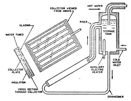
The second type of system is called a thermosyphon solar water heater. A tube type water collector is mounted at from 25-55° from horizontal depending on the season, and faced south. An insulated storage tank, about 60 gallons in capacity, is mounted so that the bottom is at least 2 feet above the top of the collector and an insulated downcomer carries cold water to the header at the bottom of the collector (Fig. 19). The system is filled with cold water and when the sun shines, the water in the tubes is heated and flows slowly up the riser into the storage tank. The process continues until tile solar radiation is no longer strong enough to heat the absorber. By the end of a typical sunny day the storage tank is full of hot water at a temperature of from 120°F on a cold winter day to 165°F on a hot summer day. For single family residences the 60 gallon tank has given satisfactory results with a 20 square foot absorber area. Steps must he taken to prevent freezing, so for Indiana an anti-freeze system should he used with a heat exchanger in the tank.
For swimming pool heating a bare-plate type solar collector with water tubes attached is often as efficient as necessary for April-September use. A pump is generally required to force the water through the tubes since a larger area is required than for the typical family hot water heating needs.
The principles used for calculating available heat for grain drying and space heating nay also be applied to industrial drying, heating, and pre-heating of air or water.
Some guidelines have been presented for determining the availability of solar energy and designing a system. An orientation of other than due south was not considered in the discussion. The effect of such an orientation of a collector is to give the greatest amount of collection in either the morning or afternoon instead of at solar noon and to decrease the daily total of collected energy. More involved calculations must he made to size the collector properly, hut you can be assured that a larger area would be required for an exposure in any other direction.
One topic which was left out of the discussion up to now is economics. What are the economics of a solar system? At the present tine the question is "up in the air." Costs today would indicate that solar heating is in general a borderline situation. But costs tomorrow may be very different. With an increase in fuel prices the cost relationships could point to the use of solar heating. If fuel were no longer available solar heating would look very attractive.
To decide whether solar heating will be economical for your particular situation, you need to take into consideration the cost of all the materials and controls required for the system and compare them with the benefits in terms of fuel saved. The cost of the system should be projected over it's expected life. The conventional fuels can be compared on a BTU Basis. One KWHR of electricity - 3412 BTU, one ft3 of natural gas - 1000 BTU, one gallon of LP gas = 92,000 BTU, and one gallon of fuel oil = 140,000 BTU. Knowing these BTU equivalents and the cost of your fuel, you can determine how much money your solar system will save or cost. Another comparison which should he made is the cost of the system vs the cost of insulation. If more BTU's can be saved for a dollar invested in insulation vs a dollar invested in a solar collector, then insulation should he the first purchase.
If you would like to build a solar heating system, you need to start planning early. Contact people with designs similar to the one you are considering and observe how their's performs. "Try out" solar heating On a small scale first, such as heating a garage or shop during the day. This will give you an idea of potential problems and performance. Finally, consider hiring a registered professional engineer to advise you on the best and most economical combination of solar collectors, storage, insulation, and auxiliary unit for your system.
RR 1/81
Cooperative Extension work in Agriculture and Home Economics, state of Indiana, Purdue University, and U.S. Department of Agriculture cooperating; H. A. Wadsworth, Director, West Lafayette, IN. Issued in furtherance of the acts of May 8 and June 30, 1914. The Cooperative Extension Service of Purdue University is an affirmative action/equal opportunity institution.