Introduction
Principles of Animal Heat Production and Loss
  Animal heat production
  Animal heat loss
  Balancing heat production with heat loss
Principles of Moisture and Odor Control
  Controlling moisture
  Controlling odor
Principles of Ventilation Design
Determining Proper Ventilation Rates
  For moisture control in winter
  For odor control in winter
  For heat buildup control in summer
Types of Ventilation Systems
  Pressure ventilation systems
  Exhaust ventilation systems
  Combination pressure/exhaust systems
Air Inlets in Exhaust Ventilation Systems
  Inlet design, location and size
  Determining the slot openings
  Cold weather air inlets
  Hot weather air inlets
  Controlling inlet air velocity
Exhaust Ventilation System Fans
  Fan selection guidelines
  Fan location
  Fan controls
  Determining fan sizes and thermostat settings
  Lowering the ventilation rate to save energy
Types of Heating Systems
  Combining heating systems
Suggestions for Ventilating Older Buildings
  Older two-story barns
  Older single-story buildings
  High ceiling buildings
Maintaining the Environmental Control System
  Providing for emergency ventilation
Summary
  Related publications
Ventilation is needed at all times in confinement livestock housing to provide oxygen, remove moisture and odors, prevent heat buildup and dilute air-contained disease organisms. Such ventilation is accomplished by either natural or mechanical means.
Natural ventilation cannot adequately insure an environmentally-controlled atmosphere, since inside temperatures and air exchange rate fluctuate with outside changes in temperatures and wind conditions. It's use in confinement livestock production, therefore, is limited to large animal housing, usually through sidewall and ridge openings. (Natural ventilation is discussed in Purdue Extension Publication AE-97.)
A mechanical ventilation system, on the other hand, consists of one or more fans, thermostats and a series of inlets. It is used where control of room temperature and air movement is a must-such as for small animals, which are susceptible to low temperatures, sudden temperature changes and stray air currents (drafts). Thus, mechanical ventilation is common in swine farrowing and nursery buildings, lambing sheds, warm dairy cattle barns and calf housing, and milk houses.
The primary disadvantages of mechanical ventilation are cost (both initial and daily operating cost) and the loss of animal heat through the ventilation system in winter. If the animals do not produce enough body heat, that which is lost must be replaced by a supplemental heating system, which requires either fossil fuels or solar energy. (For information on solar energy for livestock structures, see Purdue Extension Publication AE-99.)
Many factors affect the success and operation of environmentally-controlled livestock housing. The purpose of this publication is to review the various principles involved in environmental control, to discuss the equipment needed, and to outline their design, operation, maintenance and management.
For all but very young farm animals, optimum performance temperatures are in the range of 60-70 F (Table 1). An environmental control system can be used to keep the room temperature within this range throughout the year.
                                     Temperature (F)
			          ------------------------
  Type of animal                  Optimum          Range
-------------------------------------------------------------
  Swine
    Lactating sow                    60          50- 70
    Litter, newborn                  95          90-100
    Litter, 3 weeks                  75          70- 80
    Pre-nursery pigs, 12-30 lb.     80          75- 85
    Nursery pigs, 30-75 lb.         75          70- 80
    Growing-finishing hogs           60          50- 70
    Gestation sow and boar           60          50- 70

   Dairy
     Cows                            50          45- 70
     Calves                          70          45- 80
-------------------------------------------------------------
All animals produce heat when they convert feed into meat, milk and energy. This animal heat can be used to replace supplemental heat in the environmental control system.
The amount of heat produced depends on the type and size of animals, degree of activity, feed intake and environmental conditions (Table 2), but usually totals between 25 and 40 percent of the feed energy animals consume. More body or "sensible" heat is generated when surrounding temperatures are low to help the animals stay warm as well as grow. Young animals, however, cannot substitute enough feed for fuel, thus must have supplemental heat to perform well during cold weather.
                           Surrounding     Heat
Type of animal             temperature   produced
--------------------------------------------------
                               F          BTUs/hr.
Swine
  Sow and litter              60          1200
  Sow and litter              70          1100
  Pre-nursery pig. 12-30 lb.  80            75
  Nursery pig, 30-75 lb.      75           125
  Growing pig, 75-150 lb .    60           250
  Finishing hog, 150-220 lb.  60           350
  Gestating sow, 325 lb.      60           550
  Boar, 400 lb.               60           700
Dairy
  Cow                         50          3220
  Calf                        70           600
--------------------------------------------------
Animals lose heat to the environment in four ways: by radiation, by conduction, by convection and by evaporation through their respiratory tract (panting).
Conduction heat loss accounts for only about 10-15 percent of total animal heat loss but can affect growth because of its relationship to animal comfort. The amount of conduction heat loss is related primarily to the type of flooring used. For example, pigs can lose twice as much heat to concrete or metal slotted floors as they do to wood or plastic slotted floors, depending on how well the building foundation is insulated. Compared with concrete, bedding provides a comfort level equivalent to about a 7-15 degree rise in air temperature, depending on animal size and maturity.
To offset conduction heat loss during cold weather, mature animals will consume, more feed. In a British study, for example, sows ate an extra pound of feed per day when floor temperatures were lowered 9 degrees. Animals will also try to reduce conduction heat loss, if cold, by huddling together (piling) and by curling up to decrease the amount of contact with a cold floor. It hot, they will do the opposite-stretching out (without crowding) to put as much of their body as possible in contact with cool surfaces.
Radiant heat loss, accounting for about 30 percent of the total, is determined by the temperature of walls, ceiling and floor. The greater the temperature difference between these surfaces and the animal, the greater the radiant heat loss. Animals in an otherwise warm environment can still be uncomfortable if inside building surfaces are cold (uninsulated), causing radiant heat to be lost from the animals.
Convection heat loss (or windchill factor) makes up as much as 35 percent of total animal heat loss. It is affected most by the ventilation system and is controlled primarily by limiting air velocity around the animal to less than 50 feet per minute (fpm) in winter (less than 35 fpm for very young animals). In very hot weather when cooling is required, velocities of 150 fpm or more are best.
Solid pen partitions and hovers help break up drafts and cut the convection heat loss. However, convection heat loss on partly slotted floors is only slightly higher than that on total slotted floors. Animals show their discomfort from excessive convection heat loss by huddling together next to feeders and solid pen partitions and by bristling their coats to increase their skin surface "insulation".
Evaporative heat loss, typically 15-20 percent, can become as much as 40-50 percent of the total at high temperatures. Since pigs and cattle do not sweat, they must dissipate excess heat in warm weather directly through the skin (convection, conduction and radiation) and through increased respiration rate (evaporation heat loss). High air flow rates around the animals' heads help this evaporative process.
In general, livestock buildings are ventilated to control temperature and to remove heat produced by the animals. The exception is on very cold days when the ventilation rate needed to control moisture and odor may exceed that needed to remove heat. This calls for supplemental heat.
If constant room temperature is to be maintained, the heat produced by animals, supplemental space heaters and creep heaters must equal the total heat lost through the building walls, ceiling and floor and through the ventilation system. To determine how much additional ventilation or how much supplemental heat might be needed on a given day, you must find out how nearly both sides of the equation balance.
For example, a wintertime heat production-loss balance for a 24' x 36', moderately well insulated, 12-sow farrowing house would be calculated as follows:
   A. Temperature difference     70 F inside
                                 10 F outside

   B. Building heat loss*
      Ceiling (R=15)           3,500  BTUs/hr.
      Walls (R=12)             3,600  BTUs/hr.
      Foundation (R=1.33)     10,800  BTUs/hr.
      Floor perimeter(R=1.23)  5,900  BTUs/hr.
                             -----------------
		              23,800  BTUs/hr.

   C. Ventilation heat loss   15,600  BTUs/hr.
      (@ 20 cfm/crate)        -----------------

   D. Total heat loss (B+C)    39,400 BTUs/hr.

   E. Heat produced by
      animals (From Table 2)   13,200 BTUs/hr.

   F. Supplemental heat
      needed (D-E)             26,200 BTUs/hr.
                              (or 2,200 BTUs/sow).

*  Building heat loss calculations were made using information
presented in AE-95. "Insulating Livestock and Other Farm Buildings."
Ventilation heat loss was calculated using the technique discussed
later in "Determining Proper Ventilation Rates"
The 26,200 BTUs/hr. is the amount of space heat needed in this building to maintain a 70F inside temperature. Additional heat should be supplied for the creep area. And a higher ventilation rate for better odor control would further increase supplemental heat requirements.
The first step in proper moisture control is to understand relative humidity and its potential effects in confinement buildings. Relative humidity (RH) is the amount of water vapor in the air compared to the amount the air could carry if saturated. For example, 50 percent RH means that the air is 50 percent saturated.
Relative humidity is important considerations in confinement livestock housing for various reasons:
At present, there is no reliable equipment for sensing and controlling humidity in the corrosive environment of a livestock building. Therefore, to insure against moisture buildup, it is important to maintain a minimum level of ventilation at all times.
Waterers, feed, manure pits, wet surfaces of floors, gutters and free-stall alleys, and water vapor from the animals' lungs and skin all contribute to moisture in the air. The amount of moisture that must be removed from a confinement building depends on the type and size of livestock, air temperature and floor type.
Total-slotted floors allow moisture from manure to drain into the pit instead of having to be evaporated. This reduces by about 50 percent the moisture load which must be removed by the ventilation system, compared with solid floors. Partly-slotted floors will remove about 15 percent of the moisture, compared to solid floors.
Table 3 shows average daily moisture production for various swine and dairy animals. As building temperature and/or animal weight increases, so does the amount of moisture produced. If unvented heaters are used, further moisture (produced in the combustion process) is added to the environment, calling for ventilation rates beyond that normally required for moisture control.
                           Moisture produced if facility is -
	                    -------------------------------
                           Building  Solid   Partly    Totally
Type of animal               temp.   floor   slotted   slotted
-------------------------------------------------------------------
                              +           lb./head/day
Swine
  Sow and litter, 3 wks.      70     19       16         9.5
  Pre-nursery pig, 12-30 lb.  80      3.2      2.7       1.6
  Nursery pig, 30-75 lb.      75      3.8      3.2       1.9
  Growing pig. 75-150 lb.     60      4.2      3.6       2.1
  Finishing pig, 150-220 lb.  60      4.8      4.1       2.4
  Gestating sow and boar      60      6.0      5.1       3.0
Dairy
  Cow, freestall              50     44                 22
  Cow, stanchioned            50     36                 15
  Calf                        70     10                  5
-------------------------------------------------------------------
In some cases, the proper moisture control rate may not be high enough to achieve uniform air distribution. Therefore, small fans may be needed to circulate air within the building. These fans should be sized to deliver 1 cubic foot per minute (cfm) per square toot and located so as to move air in a circular pattern around the room, but without creating drafts on the animals.
The need for odor control depends on the type of animal housed, the waste handling system, outside air temperature and the attitude of the manager. During all but the coldest part of the year, a ventilation rate high enough to remove excess animal heat will also control odor. But a cold weather ventilation rate that just prevents moisture buildup is probably not sufficient for odor control.
Many mechanical ventilation system manufacturers design fan capacities on the basis of odor control in winter rather than moisture control. Since this rate is higher, more supplemental heat is needed to insure a constant building temperature.
The average amount of ventilation needed for adequate odor control in a typical confinement building is around four air changes per hour, which is about twice the rate for moisture control Although odor tolerance varies greatly from producer to producer, the odor control ventilation rates presented in Table 4 appear to be practical for Indiana. Higher values would decrease odor even more.
Some swine producers have designed their ventilation systems with both moisture and odor control in mind. Since a lower air flow rate in cold weather saves heat (and money) and since hog production is not adversely affected by typical odor levels, these producers normally operate their systems at the moisture control ventilation rate. Only when workers are to be in the building is the ventilation rate increased to the odor control level. This should be done at least 1/2 hour ahead of time to allow the system to bring the odor level down.
All environmentally-controlled buildings with slotted floors should remove moisture and odor control ventilation air from the manure pit and the rest of the ventilation air from the sidewall. If waste is frequently removed from the building, an odor control ventilation rate may not be needed or may at least be lower than the values given in Table 4. (See Purdue Extension Publication AE-98 for more information on pit ventilation.)
                                 Cold weather rates
			      --------------------------------
                               Moisture control*  on -
			      -------------------------               Mild       Hot
    Type of                   Fully     Partly    Solid   Odor       weather   weather
 animal or facility          slotted   slotted   floor   control     rates     rates
----------------------------------------------------------------------------------------
                                             cubic feet per minute
Swine
  Sow and litter                10        17        20      35           80       325
  Pre-nursery pig (12-30 lb.)    1.0       1.6       2       3.5         10        25
  Nursery pig (30-75 lb.)        1.5       2.5       3       5           15        35
  Growing pig (75-150 lb.        3.5       5.5       7      10           24        75
  Finishing hog (150-220 lb.)    5         5        10      18           35       120
  Gestating sow (325 lb.)        6        10        12      20           40       150
  Boar (400 lb.)                 7        12        14      24           50       180
Dairy
  Cow                           16.5      28        33      50          130       450
  Calf                           5         8.5      10      16           25       150
  Milk room (total cfm)         ---       ---        8                   25        50
  Parlor (total cfm)            ---       ---        8                   25       100
----------------------------------------------------------------------------------------
*increase moisture control ventilation rate by about 20 percent of the
solid floor value if unvented furnaces used.
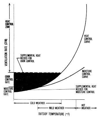
1. A confinement livestock ventilation system should be designed to remove moisture and odor in cold weather, and excess heat the rest of the year. The point at which heat begins to build up in a confinement building depends on outside temperature, insulation level, and the type and number of animals in the building. In a typical housing unit, buildup can occur at an outside temperature of 20-30 F (even lower if the building is well insulated). Above this temperature, supplemental heat is usually no longer needed, in fact, the building will become too warm unless the ventilation rate is increased. This principle is illustrated by Figure 1.
2. During winter, the ventilation system pulls or forces into the building cold air containing little moisture (Figure 2). As this cold, dry air enters, an equal volume of warm, moist air is discharged Since the temperature and moisture content of the departing air are greater than that of the entering air, heat and moisture are removed from the building.
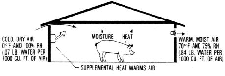
3. Warm air holds more moisture than cool air. The moisture holding capacity of air nearly doubles for every 20 degree rise in temperature. Therefore, when air is cooled below its dew point (temperature at which it holds a maximum load of water), water must crop out. In confinement buildings, this condensation occurs when warm, humid air in the livestock area comes in contact with cold, poorly-insulated building walls and windows. It could also occur as fog in livestock buildings that are subjected to a rapid rise in humidity or drop in temperature.
For example, every 1000 cubic feet of air at 60 F and 80 percent relative humidity holds about 0.66 pounds of water vapor. When this air is cooled to its dew point of 54 F, it will be saturated (100 percent RH). Then if it contacts a building surface colder than 54 F, condensation will occur (or frost, if colder than 32 F).
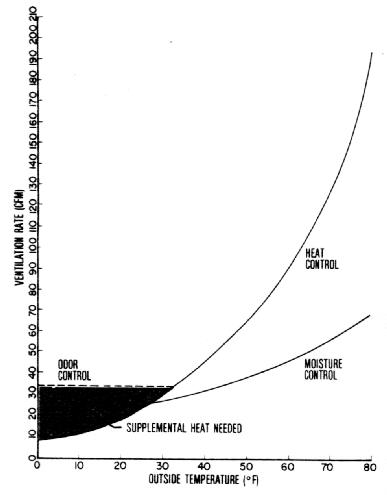
A `proper' ventilation rate must account for moisture, odor and/or heat buildup, depending on outside temperature. In illustrating below how these rates are determined, we will use an example of a well insulated, solid-floor farrowing unit that houses 30 sows with their litters.
Figure 3 summarizes, in graph form, the moisture, odor and hot weather rate from the example, with the heat production curve adjusted for estimated building heat lost. Required livestock building ventilation rates can be calculated similarly for any set of inside and outside temperatures. (Notice in the figure that the odor rate is optional in winter; its use will depend on the preference of the operator.)
While the following calculations allow for greater accuracy, Table 4 lists recommended approximate ventilation rates for various sizes of swine, dairy, cattle and sheep in confinement. The cold-weather moisture control rate is based on an outside temperature of about 2 F; while the mild weather rate is based on about 20 F, the average winter temperature for Indiana.
To determine the ventilation rate required to remove moisture, using our example 30-sow farrowing house, let's assume air temperatures of 10 F outside and 70 F inside at 80 percent relative humidity.
1. Table 3 shows that each sow and litter produces 19 pounds of moisture a day, or 570 pounds for the 30-sow house.
2. Air enters the ventilation system at 10 F containing 0.09 pound of moisture per 1000 cubic feet and is exhausted at 70 F containing 0.96 pound of moisture (For a thorough discussion on heat, moisture and air relationships, see MWPS-1."Structures and Environment Handbook." available from Farm Building Plan Service, Agricultural Engineering Department. Purdue University, West Lafayette, IN 47907 (1980 price. $8)). That means 0.87 pound of moisture is removed per 1000 cubic feet of ventilation air (0.96-0.09).
3.Therefore, the ventilation rate required to remove the moisture produced is:
   570 lb.      0.87 lb.         570 lb.          1000 cu.ft
  --------  /   -------    =   ----------    x  -----------
    day        1000 cu.ft      1440 min/day       0.87 lb.

   = 455 cu.ft
    ----------   or 15 cfm per sow and litter.
     min.
Ventilation required to remove moisture also removes heat from the building. Since 18 BTUs are needed to raise the temperature of 1000 cubic feet of air by 1 degree, the amount of heat removed by the ventilation system at the above moisture control rate is calculated as follows:
    18 BTUs       x  (70-10 F)  x   455 cu.ft.  x   60 min.
  --------------                    ----------      --------
  1000 cu.ft.- F                      min.           hr.

  = 0.018 x 60 x 455 x 60 =  29,480 BTUs/hr.
The ventilation heat loss figure is used in the heat balance equation discussed earlier to determine supplemental heat needs.
To calculate the odor control ventilation rate for our 30-sow solid-floor farrowing house, assume that the building is 84 feet long and 24 feet wide with an 8-foot ceiling.
1.Room volume is 24 feet x 84 feet x 8 feet = 16,128 cu ft.
2.For odor control in this size building, four air changes per hour are needed.
3. Thus, the ventilation rate to provide adequate odor control will be:
      16,128 cu.ft. x 4 changes  =  1075 cu.ft.
		     --------     ----------
                      60 min.         min.

      or 35.8 cfm per sow and litter.
Use 35 cfm per sow and litter, since the interior building size would be a little less than the overall dimensions given above.
If the ventilation system is operated at the odor control rate, supplemental heat needs must be calculated using the heat loss figure for this higher ventilation rate.
During summer, ventilation rates must be sufficient to keep the inside building temperature only a few degrees above the outside air temperature. In a well insulated building, inside-outside temperature difference is so small that calculation of heat loss through the walls, ceiling and floor can be ignored.
For our example, let's say that the outside air temperature is 80 F. Our goal, therefore, is to maintain an inside air temperature of 85 F or below.
1. Table 2 shows that heat production per sow and litter is about 1100 BTUs/hr. (At air temperatures higher than those in Table 2, heat production will actually be a little less than the values listed.)
2. At an air heat capacity of 18 BTUs/1000 cu.ft. per 1 F, the per-sow ventilation rate needed to remove heat produced by the animals is:
 (  1100 BTUs         18 BTUs  )
  ----------    /   -----------     /  (85 - 80 F)
 (    hr          1000 cu.ft-F )

   (  1100 BTUs     1000 cu.ft-F )
  = ----------   x  -----------      /  5 F
   (   60 min          18 BTUs   )

  =  204 cfm per sow and litter
3.Hot weather ventilation must also prevent buildup from the solar heat load on the building. In addition, heat stress in large animals at high temperatures can be relieved somewhat by passing high-velocity air around the animals. For these reasons, the ventilation rate calculated in Step 2 should be increased by about 60 percent; thus:
204 cfm x 1.60 = 326 cfm per sow and litter
An effective ventilation system for livestock housing is one that (1) forces out warm, moist, foul air, and (2) draws in fresh air, properly distributing and mixing it with building air in a draft-free manner. The system may be a pressure-type, exhaust-type, or a combination of the two. Regardless of the type, the ventilation rate recommendations selected from Table 4 will be the same.
Pressure systems use fans to push fresh air into the building and distribute it, with a baffle in front of the fan or, more commonly, a duct having carefully-placed outlet holes. Pressurized ducts should have one 2-inch opening for each 20 cfm air flow rate. Pressure exhaust outlets are usually sized at 300 square inches for every 1000 cfm of fan capacity and are located in a manner similar to Figure 4.
Pressurized systems are seldom used in cold climates during winter, because moisture can be forced through small openings into wall cavities and attics where it will wet the insulation. Also, frost may form at air leaks around and under doors, causing them to freeze shut. Thus, in colder regions, pressure systems are limited primarily to remodeled buildings where pressure outlets can be more easily constructed than inlets for exhaust ventilation.
In many areas, however, law requires that milk houses be pressure-ventilated, because exhaust ventilation could pull foul air from barns and parlors into the milk room. Pressure systems are often used for summer ventilation in large-animal housing, because high-velocity fresh air around the animals aids in cooling them. Fans are available commercially which pivot to allow exhaust ventilation in winter and pressure ventilation in summer.
Exhaust systems use fans to force air out of the building (Figure 5), thus creating a negative pressure or partial vacuum. It is this negative pressure, not the fans, that causes fresh air to be drawn into the building. And if inlets are sized and located properly, the fresh air will be distributed uniformly throughout the structure.
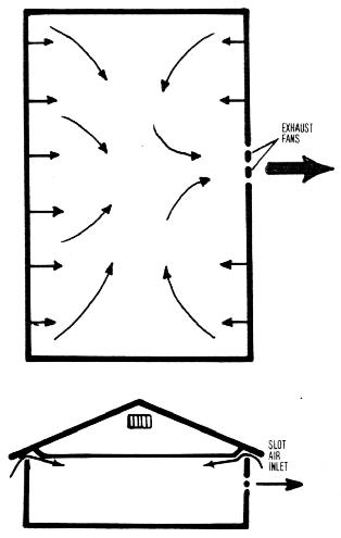
Exhaust is by far the most common ventilation system used in livestock housing, and most of the subsequent discussion will deal with this system.
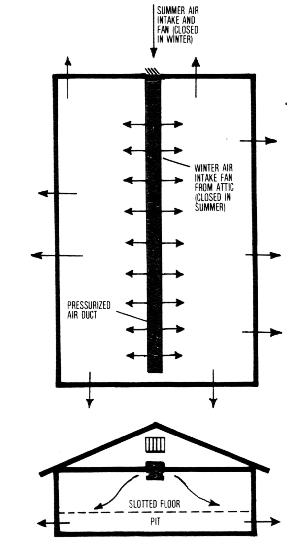
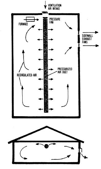
These systems include pressurized air duct inlets with sidewall exhaust fans (Figure 6). Capacity of the exhaust fans should be selected from ventilation rate information in Table 4. A fan (usually located near the ceiling and 2-4 feet away from the wall) is used to maintain pressurized air movement continuously through the duct. This fan must be sized to provide the highest ventilation rate needed (the hot weather rate from Table 4).
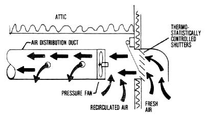
A motorized wall-intake shutter, located at the pressure fan intake and controlled by the exhaust fan thermostat, brings in fresh air direct from the outside or the attic (Figure 7). When the thermostat turns off the exhaust fans and the intake shutters close, the pressure fan continues to operate, circulating room air through the distribution duct.
In housing for young animals, control the exhaust fan and intake shutter with a timer wired in parallel with the thermostat. Even though the small animals might not produce enough heat to activate the shutters and exhaust fans, the timer will run the fans periodically to remove moisture. If unit space heaters are used, locate them at the duct intake, so that the duct will distribute the heated air throughout the room.
Two problems can result from recirculating ventilation air, especially in large animal housing-(1) dust builds up in the duct, and (2) the intake shutters may freeze. The only solution to dust buildup in the distribution duct is periodic cleaning. In the case of homemade ducts, this may mean partial disassembly; so consider ease of cleaning when ducts are fabricated.
Shutter freezing may occur in large animal housing if no supplemental heat is provided or if the circulation fan is too far from the shutters and cannot move enough warm air past them to keep them from freezing.
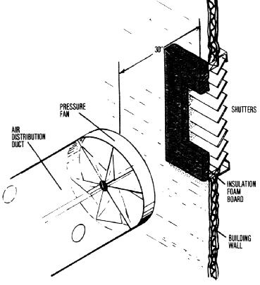
Shutter freeze-up is a serious problem since it restricts ventilation rate. Possible solutions include: using an insulated cover around the perimeter of the shutters (Figure 8), positioning a heat lamp where it can warm the shutters, or providing supplemental heat in the duct intake shutter vicinity (See Figure 6).
Distribution of Incoming air in exhaust ventilation systems depends primarily on the inlets. With proper inlet design and location, there should be no damp corners, drafts or dead air spots in the building.
Several types of air inlets work satisfactorily. One of the most successful is a continuous slot open to a source of fresh air, with an adjustable baffle to control the size of the opening (Figure 9). The slot is usually in the ceiling along the long dimension of the building near the junction of the wall and ceiling or at the center of the building width.
Here are general guidelines for locating slot air inlets in livestock buildings:
* Locate them at ceiling level so that cold incoming air has a chance to mix with warmer air before it reaches the animals. Using a battle to restrict the inlet opening increases air velocity and aids in the mixing of air.
* Locate them so that the distance to the nearest fan is no more than 75 feet but no less than 8 feet.
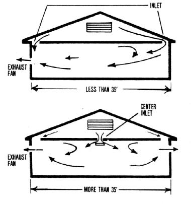
* For buildings up to 35 feet wide, place slot inlets at the ceiling along both sidewalls; for buildings wider than 35 feet, place them at the ceiling on both sidewalls and at one or more ceiling locations (Figure 10).
* Be sure that the exhaust fans in one building cannot blow foul air into the fresh air inlets of another building. Provide at least 30 feet of separation between them. (In fact, never exhaust air from one building into another. One function of a ventilation system is to dilute air containing disease organisms with fresh air. Bringing air from an adjacent animal area only concentrates the level of disease organisms.)
Inlet-opening size must match fan capacity to maintain proper air velocity. Usually, this means the inlet is sized for the highest (hot weather) ventilation rate and then closed down with a battle for lower ventilation rates.
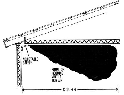
As a general rule. incoming air should be maintained at 700-1000 fpm (8-11 mph) at the point where it leaves the baffle. If the velocity is less than this, cold air settles too rapidly and can chill the animals; if greater than this, only the top portion of the room will be ventilated. When the baffle is properly adjusted, the air is `thrown out' in a distinct flume for a distance of 12-15 feet (Figure 11). This can be visualized by holding a smoke generator to the air inlet and observing the air flow.
Avoid placing obstructions on the ceiling within 6 feet or so of the inlet; they can deflect the incoming cold air down on the animals before it is properly mixed and tempered. Also, avoid corrugated ceiling liners in this first 6-8 feet if the corrugations would run perpendicular to air flow. This is especially important for small animals, which are highly susceptible to drafts.
The slot width should be such as to deliver the proper amount of air at a static pressure differential (difference in atmospheric pressure inside and outside the building) of about 0.04 inch (about 1/25 of an inch) of water pressure. At this pressure differential, a 1-inch wide, 1-foot long slot will deliver 50 cfm. Similarly, a 2-inch wide, 1-foot long slot will deliver 100 cfm.
Example: To calculate the proper slot openings in hot and cold weather, let's again use our example 24' x 84', 30-sow farrowing house. Following the principles outlined above, we will place the exhaust fans in the center of the south wall, leave an 8-foot clear section (no inlets) to each side of the fans, and locate inlets at the ceiling on the long sides of the room.
1. Total slot inlet length is: (building length 2) - (length of clear section on both sides of fan bank)
or (84 ft. X 2) - 16 ft. 154 ft.
2. Maximum ventilation rate per foot of inlet is: (hot weather rate, from Table 4 x no. of sows) / total slot inlet length
         (325 cfm X 30)
  or     -------------- =   63.3 cfm./ft.
           154 ft.
3. Since a 1-inch wide slot provides 50 cfm per foot of length, necessary slot width in hot weather is:
      63.3 cfm
     ------------ =  1.26 or about 1 1/4 in. wide
      50 cfm/in.
4. In cold weather. the ventilation rare needed for moisture control is much less: thus, minimum ventilation rate per foot of slot length is: (cold weather moisture control rate, from Table 4 x no. of sows) / total slot inlet length
        (20 cfm x 30)
     or ------------- = 3.9 cfm/ft
         154 ft.
5. To provide this cold-weather rate, the slot must be partially closed, using the baffle, to
       3.9cfm
      ---------  = 0.078, or about 3/32 in wide
      50 cfm/in
The baffle should be adjustable to permit proper air distribution at any ventilation rate between the minimum and maximum. Sometimes the cold weather rate is so low that it is difficult to adjust the baffle to obtain a small enough slot opening. In these cases, a good solution is to close off every other 8-foot section of inlet and double the slot opening in the alternate 8-foot sections.
In very cold weather, frost can occur at the slot inlet at the point where the cold, dry incoming air meets the warm, moist air in the building. Insulated baffles help minimize this problem.
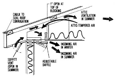
In winter, all incoming fresh air should come from the attic. This tempers the air and can also decrease frost problems at the inlet. The attic space is warmed both by the sun during the day and by heat from the animal area lost through the ceiling. An average of about 7 degrees increase in air temperature (15 degrees increase during the day and 4 degrees at night) may occur, assuming a ceiling insulation R-value of 13.
Unfortunately there is not much solar effect on cloudy days. And under some night weather conditions, air temperature can actually decrease as it passes through the attic as heat from the roof is radiated back to the cold winter sky.
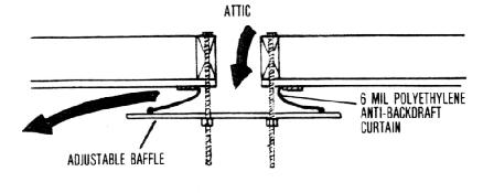
The moisture control fans should run continuously, because when fans are off, the warm barn air can rise through the slot, condense on the underside of the cold roof and drip down, wetting the attic insulation.
If the cold weather fan is timer controlled, use a plastic curtain on the slot to help prevent backdrafting Figure 12)
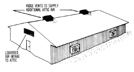
Air can be admitted to the attic through soffit openings, if slot inlets are located in the center of the room. If the inlets are along the room perimeter, use large louvers built in the gable ends of the building (Figure 13). Ridge ventilators may also be needed in very long buildings. Screen the louvers on the inside with 1/2-inch mesh hardware cloth. Provide about 1 square inch of attic opening for every 2 cfm of mild-weather ventilation rate (Table 4).
In hot weather, pull fresh air directly from the outside instead of bringing it through the hot attic. To do this, build slides or doors, which can be closed in winter, in the soffit area under the eaves (see Figure 9). This design permits some of the air entering at the soffit opening to ventilate the attic, thus lowering the ceiling temperature above the animals.
Screen the soffit opening with 1/2-inch mesh hardware cloth. Smaller-mesh screen plugs rapidly with dust and restricts air flow.
Air intake control is critical to good ventilation. Each time the fan ventilation rate changes, size of the slot inlet should also be changed. While the slot baffle can be adjusted manually, environmental control is best if they can be adjusted automatically. Manually-adjusted baffles should be designed so they can be winch-and-cable operated from one location in the building.
Power-operated baffles are available commercially to automate the winch-and-cable system. Most automatic units sense the change in pressure when additional fans come on, and inlet baffles open enough to maintain a pre-set negative pressure.
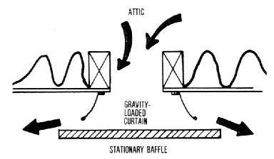
Gravity-loaded curtains can be used in place of a baffle (Figure 14). Curtain-controlled slot openings are self-adjusting, but are not as precise as a rigid cattle control The greater the air flow required by the fans, the wider the curtains swing open. Plastic curtains tend to become less flexible with age. They should be checked at least once a year and replaced as needed.
To insure uniform ventilation, it is important to plug all unplanned openings. All doors and windows must be closed when the ventilation system is running, otherwise air will not be drawn in through the slot inlets.
Selecting the `right' fan is not complicated it dealing with a reputable farm ventilation company. Select a fan capable of moving the required amount of air against 1/8 inch or at least 1/10 inch of water column static pressure. Although normal operation for ventilation fans is at a much lower pressure (slot air inlets are sized for 1/25 inch of water static pressure), they often must operate under less-than-local conditions.
The amount of air that a fan can move in a "free air" environment is not a measure of its ability to perform against wind pressure. A 1/8-inch water pressure rating means the fan will deliver the stated amount of air against pressure equivalent to a 15-mph wind This is a major limitation of variable-speed fans, which have poor pressure ratings when operated at low speeds. To insure acceptable performance, purchase fans which have been tested under the Air Moving and Conditioning Association, Inc. (AMCA) standard test code.
Also look for the fan's cfm/watt rating when operated against 1/8-inch water static pressure; this is an indication of its operating cost. Fans with a cfm/watt rating of at least 15 will be efficient. Larger fans are usually more efficient than small ones; but they will not be a bargain if more air (and heat) is exhausted in winter than is necessary for good ventilation.
Diameter is not a reliable indicator of a fan's capacity. As shown in Table 5, a fan's capacity is not directly proportional to its diameter.
   Diameter        Horse-
                   power        Speed       Capacity"
-------------------------------------------------------------------
    in.            hp           rpm            cfm

Single- and multi-speed fans

     7             1/20        3,000           150
     8             1/20        3,000           365
    10             1/28        1,550           600
                   1/5         3,000           738
    12             1/12        1,725           980
                   1/6         1,725         1,000
    14             1/4         1,725         1,570
    16             1/4         1,725         2,380
    16 (4-speed)   1/4           800           700
                               1,060         1,150
                               1,350         1,600
                               1,600         2,200
    18             1/4         1,725         3,000
                   1/3         1,725         3,400
    20             1/6         1,725         2,750
                   1/4         1,075         3,300
                   1/3         1,725         3,160
    24             1/4           625         4,000
                   1/3           780         4,500
                   1/2           770         5,800
                   3/4           875         6,750
    30             1/4           500         5,000
                   1/3           500         6,000
                   1/2           555         7,800
                   3/4           625         9,150
    36             1/3           425         7,750
                   1/2           800        10,200
                   3/4           545        11,100
                     1           610        12,750
    48               1           525        19,230
    48 (2-speed)   3/4           317         8,400
                                 525        16,826

Variable-speed fans         (max)      (min.)      (max.)
    14             1/8       1,750       112       1,630
    16             1/3       1,725       845       2,250
    18             1/3       1,510       570       3,100
                   1/3       1,625       400       3,775
    24             1/4       1,075     1,490       4,000
                   1/3       1,050       800       4,400
    36             1/2         810       600       8,200
-----------------------------------------------------------------------
*All single-speed capacities are at 1/8 or 1/10 inch water pressure
Fans used for animal housing ventilation should be designed specifically for that purpose. Ones with stainless steel and fiberglass shutters, blades and housing withstand corrosion best, with certain aluminum and epoxy treatments being adequate under most conditions.
Fan motors should be totally enclosed and of a split-phase or capacitor type. To prevent motor damage, fans should be protected by time-delay fuses or thermal-overload devices. Place each fan on a separate circuit to eliminate shutdown of the entire ventilation system if one motor blows a fuse.
Location has very little effect on air distribution. Even so, fans should be placed in the downwind (in winter) wall, where possible, either uniformly spaced or grouped together in a bank. A fan bank is best, since it allows the controls and fans to be placed close together for convenient servicing and makes more of the sidewall available for air inlets. Since the distance from inlets to fans should be no more than 75 feet, long buildings may require more than one fan bank.
Avoid placing fans in feed annexes or other uninsulated areas where warm, moist ventilation air can cool and condense on cold walls or floors. Also, if fans must be located on the west or north where they exhaust against strong winds, protect with hoods or upchutes, or place a windbreak 5-10 feet from the building. (For more on wind control, see Purdue Extension Publication AE-102.)
All fans should have anti-backdraft shutters. If fans are operated intermittently during winter months, position shutters on the inside (animal side) of the fan to decrease freezing problems.
These additional guidelines should be considered in deciding where to place exhaust fans;
* Locate fans at least 8 feet from air inlets, entry doors and other openings.
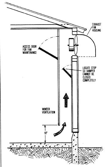
* In older barns or in newer ones that are lightly insulated, build around the cold weather ventilation fan a duct 12 inches deep and as wide as the fan frame to draw cooler air from the floor (Figure 15). Extend the duct to within 18 inches of the floor. Cut an access door in the duct immediately behind the fan for maintenance and to bypass the duct floor inlet in hot weather. This technique is useful where the heat balance is marginal and where the ducts can be protected from animal abuse.
* In slotted-floor buildings, locate cold weather ventilation fans to exhaust air from the manure pit area. Pit fans should have pressure ratings equal to or better than the wall fans. Otherwise, the wall fans could overcome the pit fans and draw air from the pit into the animal area, especially if there are insufficient fresh air inlet openings.
Controls should allow for full-range ventilation with a gradual change in ventilation rate within this range. This requires accurate sensing of environmental temperature and a range of fan capacities.
Good-quality thermostats are simple and reliable. Choose one designed especially for livestock housing and having an off-on range of 5 degrees or less. Locate it in the center of the building, out of the reach of animals, away from cold walls and where it can be easily seen and adjusted. Keep it out of the path of furnace exhausts, ventilation inlet air or direct sunlight.
For safety, provide a manual disconnect switch for each fan within sight of the fan, or a switch that can be locked in the "off" position to prevent fans from accidentally being turned on during servicing.
Most variable-speed fans can be controlled to deliver as little as 10-20 percent of their rated capacity. The control consists of a solid-state electronic speed-control and a thermistor heat-sensor. The heat-sensor changes the voltage supplied to the fan motor as the temperature changes (within a range of about 8 F), which, in turn, changes fan speed and capacity.
A livestock housing environmental control system (fans and heaters) should be able to provide the optimum temperatures recommended in Table 1. Even though ventilation is not an exact science, fan capacities and thermostat settings can be chosen to produce conditions that closely parallel the ventilation curve as shown in Figure 1.
Most thermostats have an on-off range of about 5 degrees; and fans and heaters are normally staged to come on in 3-5 degree increments. Always take care to prevent the ventilation and heating systems from working against each other. The heater should never operate if the heat control ventilation rate is greater than that needed to control moisture (or sometimes odor).
To determine fan sizes and thermostat settings that will provide for optimum temperatures in a given livestock facility, first find the recommended ventilation rates for that building from Table 4, then select appropriate fan sizes from Table 5. For example, in our solid-floor, 30-sow farrowing house, Table 4 shows that the ventilation rates must be:
  Cold weather:
    (Moisture control) 30 x  20 =   600 cfm
    (Odor control)     30 x  35 =  1050 cfm
   Mild weather:       30 x  80 =  2400 cfm
   Hot weather:        30 x 325 =  9750 cfm
To maintain a desirable temperature for the sow and litter (Table 1), we could choose the fans (from Table 5) and thermostat settings shown in Table 6. See Purdue Extension Publication AE-109 for a detailed example of how this is determined.
                                      Ventilation
Fan size and capacity                  rate (cfm)     Operation
--------------------------------------------------------------------

Cold weather ventilation
  10-in fan at 600 cfm (1/28 hp)        600      Continuous operation
  10-in fan at 600 cfm (1/28 hp)       1200      On as needed for odor control
                                                    in winter, on at 75 F
  Furnace                                        On at 68 F: off at 73 F

Mild weather ventilation
  12-in fan at 1000 cfm (1/6 hp)       2200      On at 77 F

Hot weather ventilation
  18-in, fan at 3400 cfm (1/3 hp)      5600      On at 80 F
  24-in, fan at 4500 cfm (1/3 hp)      10100     On at 83 F
--------------------------------------------------------------------
Fan capacity needed for moisture removal alone is not very great--e.g., 200 cfm for a 20-sow, total-slotted floor farrowing house (Table 4). Up to now there were only a few fans on the market that could deliver such a low ventilation rate; however, some manufacturers are beginning to actively market reliable ventilation fans in the 150-500 cfm range.
If the smallest fan available is larger than needed for moisture control, you should use some means of lowering the fan capacity--perhaps a timer control (to run a 1000-cfm fan 20 percent of the time) or a variable-speed fan on its low setting. A better solution, however, would be to use the best small, single-speed fan available, and construct a duct over it (as shown in Figure 15) to exhaust the air from a point about 18 inches from the floor.
Install a sliding damper in the duct; this will restrict air flow to an acceptable level, while still allowing the fan to operate against changing wind pressures. Also build a `stop' into the duct to prevent the damper from closing completely so that cooling air can always get to the fan motor.
Supplemental heat is required if the animals do not generate enough heat themselves to maintain optimum temperatures in cold weather. A well-insulated building with a properly controlled ventilation system can significantly minimize the amount of extra heat needed.
The cross-hatched areas in Figure 3 show the conditions under which additional heat must be provided in our 30-sow farrowing house example. Table 7 gives the supplemental heat requirements for typical livestock housing in Indiana using the ventilation rates shown in Table 4.
                                         Supplemental heat
					 ---------------------
                                 Inside   Slotted    Bedded/
  Animal                         temp.     floor     scraped
--------------------------------------------------------------
						BTUs/hr.
  Swine
    Sow and litter                60 F                3500
    Sow and litter                70 F     3000
                                  80 F     4000
    Pre-nursery pig (12-30 lb.)   80 F      350
    Nursery pig (30-75 lb.)       65 F                 450
                                  75 F      350
    Growing pig (75-150 lb.)                600
  Dairy calf                               1000       1000
--------------------------------------------------------------
 *Sized for the odor control ventilation rate in a a moderately
well-insulated building. Additional creep heat is needed for young
animals in farrowing, nursery and calf barns. Size creep heaters at
about half the space needs shown here.
There are four types of heating systems presently being used for livestock housing-overhead radiant heating, floor heating, unit or space heating and make-up air heating. Some swine producers feel that a combination of systems is best, especially in the farrowing and nursery houses.
Overhead-radiant heaters and floor heat are used in creep areas and in the sleeping area for large animals instead of bedding. Often both types are used in the creep for the first day or two after farrowing; then the overhead heat is turned off as the little pigs become acclimated. Overhead heaters allow unconfined animals to find their best environment by moving closer to or farther from the heat.
Floor heat is supplied either by electric resistance cable or hot water pipes buried in concrete or by electrical heating coils in fiberglass pads placed over an existing floor. Heat pads, used mainly for young pigs, supply from 20 to 40 watts per square foot and are available with thermostatic controls to moderate temperatures as pigs become older. Never use insulation or bedding on top of heated floors, but do consider including waterproof insulation underneath a heated floor slab if planning new construction.
Unit or space heaters heat and recirculate the air using electric resistance or fuel-fired furnaces (either vented or unvented). Their main disadvantage is that they recirculate dusty, wet, corrosive air through the furnace, often resulting in high maintenance. Generally, it's best to place them such that they will blow along the coldest wall; this both intercepts cold drafts and cuts radiant heat losses to the wall. Where more than one heater is used, arrange them to create a circular air motion within the room.
Make-up air heaters are direct-gas-fired (unvented) units which are located outside the livestock building. The furnace operates by heating incoming ventilation air. Fuel flow to the burner is usually modulated to maintain a constant exit air temperature. Make-up heaters must be sized carefully to prevent overrunning the cold weather exhaust fans. Since they supply part of the fresh air needed. the slot air inlet opening should be closed down accordingly.
Unvented heaters provide a uniform building temperature and are about 90 percent efficient because they blow the products of combustion into the animal area along with the heat. Unfortunately, one of these products is water-about a pound produced for each pound of propane burned. Therefore, to remove this extra moisture, the cold weather ventilation system should be operated at a higher rate. (See Purdue Extension Publication AE-109 for help in making this calculation.)
Frequently, more than one heating system is used to provide needed animal comfort. Creep heaters are normally required in farrowing and nursery areas. If floor heat is used in the farrowing creep, plan on about 40 BTUs per square foot (about 500 BTUs per hour total) plus about 250 watts (850-900 BTUs per hour) from overhead radiant heaters for the first few days after farrowing. If no floor heat is used, provide 2200 BTUs per hour per litter in the creep with overhead heaters. The creep heat-per-litter recommendation in nursery buildings is the same as for farrowing buildings.
Locate furnace thermostats away from the effect of ventilation air inlets and direct sunlight, and protect from animal contact. Placing both furnace and fan controls in the center of the room, about 4 feet off the floor is usually the best choice. Set heater thermostats at the temperature you want maintained. In the case of heater controls not calibrated in degrees, be sure to use an accurate thermometer for adjusting the heater controls, and read from this same thermometer to check the accuracy of fan thermostats.
Older buildings usually present some unique ventilation problems. Often, the producer must settle for a less-than-ideal environment because of low insulation levels and difficulty in getting uniform distribution of incoming air.
Loose-fitting windows, cracks in the siding and other unplanned openings make it almost impossible to obtain recommended air flow rates and uniform air distribution. In many cases, the ventilation fan simply pulls air in through these cracks, doors and windows. The result is that some areas are overventilated while others are underventilated.
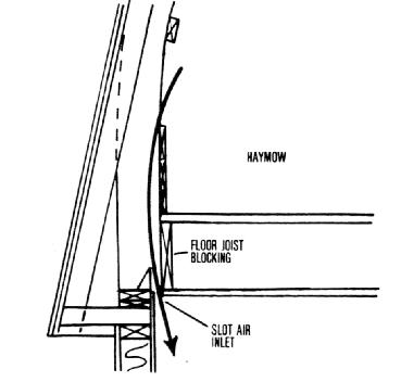
Two-story barns with haymow floors can be ventilated in one of three ways. The most costly is to install a ceiling under the mow floor joists with a standard baffled ceiling slot inlet. The joist cavity must be blocked off around the air inlet with a tight-fitting header (Figure 16) to prevent cold intake air from circulating within the cavity and destroying the insulation value of the haymow. Design the inlets so that air can be brought in directly from outside in summer instead of going through the haymow.
A layer of tightly-stacked bales on the mow floor provides the insulation value of a 6-inch fiberglass batt. As with all insulation, the hay should be protected from moisture; therefore, lay a 6-mil sheet of plastic on the mow floor before stacking the bales, and be sure to keep hay and chaff away from the air inlet.
The second method is to use a fan-pressurized tube inlet as shown in Figures 5 and 6. The recirculation feature of the pressure duct overcomes the air distribution problems caused by the exposed ceiling joists.
A third method is simply to drill a series of 2-inch holes (one for every 20 cfm of ventilation air needed) in the haymow floor around the perimeter or wherever the inlet is to be located, then place a baffle under the inlets, fastened to the underside of the floor joists. The baffle should extend out at least 1 foot away from the air inlet on each side. Use a slide valve in the attic to close off part of the air inlet area in cold weather. And consider using hovers in the pen areas directly below the inlets if drafts are a problem.
For this type of structure, design a conventional slot inlet or use a pressurized inlet system. One workable solution is a homemade duct located directly beneath the ceiling to supply air either from the attic or directly from outside. Construct a baffled slot opening along the duct. The duct area should be sized for an air speed of 600 fpm.
In our 30-sow farrowing house, which was found to have a hot weather ventilation rate of 9750 cfm, an air supply duct placed down the center of the building should have a cross sectional area of 16.25 square feet (9750 cfm / 600 fpm). A duct sized 6 1/2 feet wide and 2% feet deep would provide this area and should be insulated for wintertime use. The duct area could be reduced by half if the air were brought in at the center or at both ends.
A high ceiling presents another ventilation problem in an older building. The extra height can cause drafts on the animals and is too large to heat economically. There are two solutions.
The most costly is to lower the ceiling to 7-8 feet. If a slot air inlet is to be used, construct a horizontal ceiling, since air distribution is apt to be unpredictable when the slot inlet is placed next to a sloped ceiling.
The other solution is to use hovers over the animal resting areas (Figure 17). This works especially well with floor heat. Cover about one-third of a pen (or half the creep area) to minimize drafts on the animals. Hovers need not be insulated to be effective. In fact, plexiglass or a heavy sheet of clear plastic mounted on a wood or metal frame makes an excellent hover and also allows the producer to observe the animals. Hovers should be located just above animal height.
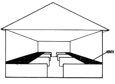
Studies have shown that hovers are more effective in reducing vertical drafts than solid covers placed over a slotted floor. Solid walls and pen partitions around the resting area are also beneficial, particularly when adjacent to the hover.
As is the case for all mechanical equipment, a livestock environmental control system requires periodical maintenance. And because continuous, successful operation of a ventilation system is so important for maximizing animal performance and minimizing energy utilization, such maintenance should be conscientious and thorough. Keep the following points in mind when developing a maintenance schedule for your particular livestock facilities;
* Fans used for pit ventilation are exposed to corrosive manure gases and will deteriorate faster and require more maintenance than wall fans.
* Most ventilation fans have sealed bearings and do not require lubrication. However, other bearings should be oiled with a few drops of SAE No. 10 non-detergent oil twice a year. Never overlubricate.
* Apply a few drops of graphite to fan shutter hinges at least four times a year.
* Check fans with belt drives at least once a month to make certain belts are at proper tension and in correct alignment. If too tight, belts can cause excessive bearing wear, if too loose, excessive slippage and belt wear can result.
* Dirty thermostats will not sense temperature changes accurately or rapidly. Dust also acts as insulation on fan motors, preventing proper cooling and, if allowed to build up, can result in motor overheating. Clean motors and controls at least three times a year.
* Make certain that shutters open and close freely. Dirty fan shutters can decrease fan efficiency by as much as a 25 percent. Clean fan blades and shutters once a month. Be sure to shut off the power to thermostatically-controlled fans before attempting to service them.
* Every year, clean and repaint chipped spots on fans and shutters to prevent further corrosion.
* During winter months, cover hot weather fans with a layer of insulation and plastic on the warm (or animal) side of the fans. Or operate them briefly every few weeks; this prevents ice and dust buildup on motors and shutters, which could cause them to stall when activated by the thermostat control.
* At least once a month during the heating season, remove dust from heater cooling fins and filters, and check gas jets and safety shut-off valves for proper operation.
* Check slot air inlets at least twice a year for debris. In a new system, pieces of the vapor barrier or insulation may break loose and block the inlet.
* Check pressurized air ducts for dust accumulation at least once a year. Dust will build up since these units recirculate large amounts of room air.
* Check gable and soffit air inlets once a year for blockages. Use 1/2-inch mesh hardware cloth to keep out birds and rodents.
* In spring, remove any furnace air filters which were placed over attic air inlets in winter to stop snow blow-in. Clean or replace filters before the next winter.
* Once a year, check plastic backdraft and gravity-loaded baffle curtains used on slot air in lets. They can become brittle with age and require replacement.
* Mow and clear grass and vegetation away from pit fan discharges.
Provision for emergency ventilation is essential in all environmentally-controlled confinement buildings because of the danger of animal suffocation. This can be as simple as several manually-opened sidewall doors or as sophisticated as an electric generator system which starts automatically to power the fans in case of electrical failure. Magnet-locked ventilation doors, which drop open when electrical power is cut off or room temperature rises sharply, are also available commercially.
Consider installing an alarm system to let you know when electrical power is off. In addition, regularly test your emergency ventilation and alarm systems to make sure everything is in good working order when needed.
Proper management of an environmental control system for livestock housing depends, to a large extent, on the operator's understanding of the design principles discussed in this publication. The economic rewards of a well-designed, properly-operated system can be substantial, because of improved animal performance and lower heating-cooling costs.
Although reliable, sophisticated controls and equipment are available, most must be "fine tuned" to match the exact needs of your particular facilities. Then they must be continually maintained to provide efficient, dependable operation.
Single copies of the following "Energy Management in Agriculture" publications are available free to Indiana residents from their county Cooperative Extension Service office or by writing to CES Mailing Room, AGAD Building, Purdue University, West Lafayette, IN 47907:
"Insulation of Livestock and Other Farm Buildings" (AE-95)
"Manure Pit Ventilation in Confinement Livestock Buildings" (AE-98)
"Natural Ventilation for Livestock Housing" (AE-97)
"Solar Heating Systems for Livestock Buildings" (AE-99)
"Troubleshooting Livestock Environmental Control Systems" (AE-100)
"Wind and Snow Control for the Farmstead" (AE-102)
"Worksheet for Sizing Livestock Housing Environmental Control Systems" (AE-109)
New 6/80
Cooperative Extension work in Agriculture and Home Economics, state of Indiana, Purdue University, and U.S. Department of Agriculture cooperating; HA. Wadsworth, Director, West Lafayette. IN. Issued in furtherance of the acts of May 8 and June 30, 1914. Purdue University Cooperative Extension Service is an equal opportunity/equal access institution.