AE-99
Factors Affecting Solar Energy Utilization

Types of Solar Heating Systems
  The passive system
  The active system

Collector Units for Active Systems
  Active collector type and design
  Collector orientation, location and size
  Low- vs. high-temperature collectors

Heat Storage--Materials and Types
  Heat storage materials
  Size of a heat storage
  In-building vs. separate heat storage
  Insulating heat storages

Procedures for Selecting and Sizing Solar Heating Systems
  Passive building collection
  Active air-type collection with integral storage
  Active air-type collection with separate storage
  Active water-type collection

Additional Considerations
Fuel cost represents a significant--and growing--portion of the total cost of livestock production, The availability of a cheap, efficient source of heat energy, therefore, would be a benefit to many confinement livestock operations. One such source is solar energy, because it is abundant and inexhaustible.
The purpose of this publication is to help you, the livestock producer, evaluate the potentials of solar heating for your particular situation. Discussed are the major factors affecting the use of solar energy, the two types of solar systems and where they best `fit,' plus collection' and storage principles and components. Instructions (with examples) are then provided for calculating your buildings' energy needs, and for selecting and using a solar system that meets those needs.
Here are two things that limit, to some extent, the sun's potential as an energy source to heat a livestock building. Keep them in mind when making your evaluations.
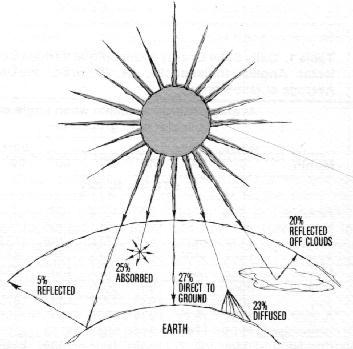
Solar availability. Everyday, the sun beams to earth about 10,560 BTUs of energy per square foot. However, because of the earth's rotation and seasonal changes, usually much less than this is available at the earth's surface. Cloud cover, air pollution, reflection and atmospheric absorption further reduce the amount of solar energy received (Figure 1). In fact, the average daily total (on a horizontal surface) in the Indianapolis area is only 1290 BTUs/sq.ft., ranging from 491 BTUs in December to 2042 in June (Table 1).
              Average energy available when angle of
                     collector with ground is-
      ------------------------------------------
           Horiz. 4/12                     Vert.
  Month       0    18    30    45    60    90 (degrees)
------------------------------------------------
                      BTU/sq. ft.- day

  January    526   798   927  1034  1081   994
  February   797  1151  1195  1287  1306  1119
  March     1184  1431  1515  1550  1498  1137
  April     1481  1605  1616  1553  1403   841
  May       1828  1841  1781  1631  1398   684
  June      2042  1996  1897  1696  1412   596
  July      2040  2018  1933  1747  1481   675
  August    1832  1833  1934  1818  1605   885
  September 1513  1747  1814  1813  1710  1205
  October   1094  1417  1548  1635  1629  1340
  November   662   966  1105  1221  1266  1142
  December   491   773   906  1024  1082  1017
------------------------------------------------
Conservation. Energy conservation in a livestock building is particularly important when solar heat is used, because the amount which can be collected on most days will be marginal. In confinement livestock housing, `conservation' means making the heat produced by the animals go as far as possible. Proper building insulation and ventilation system management permit moisture and odor removal while minimizing heat loss, (See Purdue Extension Publications AE-95, AE-96 and AE-97 for more information on insulation and ventilation in livestock buildings.)
There are two systems used to collect solar energy for heating livestock buildings-passive and active. Passive systems require no separate solar collectors and no medium to transfer heat from the collector to the livestock. The building itself does the collecting.
Active systems include collector units and fans or pumps that push solar-heated air or liquid to where the heat may be stored or used by livestock. Since heat can be transferred from one location to another, active systems are much more versatile than passive systems.
A passive solar system is designed to take advantage of seasonal changes in the sun's angle. A combination of south-facing `solar windows' and a roof overhang enables solar energy to be collected in winter, but prevents its entrance in summer (Figure 2).
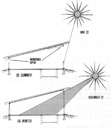
Passive solar heating simply means radiation passing through glass or plastic windows, being absorbed by the objects it strikes (walls, floor, pen partitions and animals) and warming the environment. The value of heat buildup on a sunny winter day may well meet the animals' heat requirements during daylight hours. Unfortunately, the same windows which allow solar energy to enter by day also let heat escape at night. The result can be a drastic cycling of temperatures and excessive moisture condensation on window surfaces.
In Indiana, the passive system provides the most benefit during early spring and late fall, and on mild winter days when the temperature difference between inside and outside is 30F or less. Also, it is best suited to larger (older) animals, since farrowing and nursery barns would require much supplemental heat, especially at night, to overcome that lost through window areas.
Passive system design considerations. Building orientation is the first consideration in designing a passive system, since the building itself serves as the solar collector. Length of the building should run east and west to take advantage of the sun, which is low in the southern sky in winter. Horizontal shades (usually roof extensions) are needed to protect the southern-exposed windows from the sun in summer, yet not interfere with its penetration in winter.
Because of the possibility of drastic temperature fluctuation, satisfactory conditions are difficult to obtain in a passive-heated facility, even if well managed. The job can be simplified, however, by (1) adding recommended insulation levels to walls and ceiling or roof, (2) providing `insulating glass' on the windows, (3) using insulating covers over windows at night, and (4) using a ventilation system which is thermostatically-controlled. On sunny winter days when there is enough heat, a high ventilation rate is possible for drying up condensation and controlling odor.
An active system requires facilities and equipment for collecting, transferring and storing solar energy. This allows you to collect solar heat at one location and move it by fans or pumps for use or storage elsewhere.
For example, the solar collector could be located at a farrowing house and the heat transferred to a nearby grain dryer at a time when heat demand for farrowing is low. In addition, the heat storage facility makes it possible to `even out' temperature extremes from day to night.
Most confinement livestock structures can be more easily adapted to air-type solar systems than to water systems, because they have existing ventilation systems which can be used to distribute the heated air. Notable exceptions where solar-heated water can be used to an advantage include farrowing houses which have floor heat and dairy operations for heating water to clean equipment.
Type, design, orientation and location are all factors that affect the ability of an active solar collector to absorb the sun's heat. The desired temperature of the heated air or water depends on its intended use. These factors are discussed in this section. (Additional information on solar collectors is found in Purdue Extension Publication AE-88.)
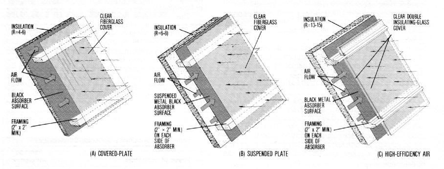
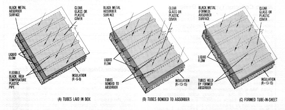
Many different types of solar energy collectors are being used on Midwestern farms, but all have two common characteristics-(1) a black-painted surface to absorb the sun's rays, causing an increase in the temperature of that surface and (2) a transfer medium, usually air or water, to pick up the heat absorbed and transfer it to storage or point of use. Most collectors also have cover plates over the absorber surfaces to help reduce both convection heat loss to wind passing over the collector and radiant heat loss. Typical air- and water-type solar collectors are shown in Figures 3 and 4.
Commonly, cover plates are made of either glass, fiberglass or plastic. Single- or double-strength window glass has a transmissivity of 87 percent. That means 87 percent of the incoming solar radiation passes through to the black absorber surface; the rest is either reflected or absorbed by the glass.
Greenhouse-grade fiberglass is the material most often used for collector cover plates on farms in the Midwest. It has a transmissivity somewhat less than glass (approximately 80 percent), but is more resistant to breakage.
Plastic films or sheets are also used, but only a few types can withstand the sun's rays for more than a year or two before becoming discolored and brittle. The transmissivity of plastic is high (92 percent), but radiant heat losses of up to 30 percent can occur back through the cover (compared to almost none with glass or fiberglass).
The efficiency of an active solar collector is measured by its effectiveness in transmitting energy, through the cover plate and then absorbing and retaining that energy on its absorber surface. Efficiency is influenced by the amount of insulation used in collector construction and by the rate at which the transfer medium flows through the collector. Depending on design and orientation, stationary collectors can capture from 25-60 percent of the available energy. Table 2 shows the efficiencies for typical on-farm collectors.
                                           Average
  Types of collectors                      efficiency
------------------------------------------------------
  Vertical wall collectors (winter use only)
    Passive solar window (fiberglass)       80 pct.**
    Concrete block wall (air-type)          50 pct.

  Collectors at 45o-65o tilt (year-round use)
    Plastic-tube (water-type, high-temp.)   35 pct.
    Bare-plate (air-type)                   30 pct.
    Covered-plate (air-type)                35 pct.
    Covered-suspended plate (air-type)      40 pct.
    Two-cover-suspended plate (air-type)    45 pct.
-------------------------------------------------------
* The air-type collectors here are all low-temperature units:
high-temperature collectors are about 10 percent less efficient
Reflectors can be used to increase collector efficiencies by 5-10
percent. A collector mounted on 3/12 and 4/12 roof slopes (about 18
angle) may have a slightly lower average annual efficiency than at a
45-65 degree slope: but more importantly, roof collector efficiency
will be low in winter and high in summer, due to the changing angle at
which the sun strikes it.

** This is not a true efficiency value since heat losses are not
included. Heat losses are variable, depending on building insulation
levels and other factors, but overall efficiency is usually 10 percent
or less.
Solar collectors are most effective if the energy-absorbing surface is perpendicular to the sun's rays (Figure 5). Although collectors are available which can be adjusted to track or follow the sun across the sky, the expense and complexity of such equipment normally cannot be justified for farm use. Instead, stationary collectors are used on walls or roofs, or as free-standing units.
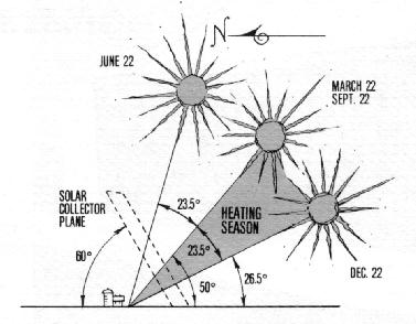
The most efficient tilt for a stationary collector in Indiana is an angle of about 60 degrees above ground level for winter heating and about 50 degrees for year-round solar collection. Roof collectors are sometimes used on conventional livestock buildings (3/12 or 4/12 slope roof), but are not as effective because of the low angle at which the winter sun strikes the roof surface (Figure 6).
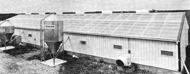
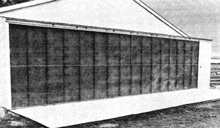
Vertical sidewall collectors exposed to the south are popular for farm use because of their simple construction and relatively high efficiency in winter. Many sidewall systems also utilize white-painted, hinged cover panels. In summer, the panels close off the collector to reduce solar radiation; when dropped open in winter, their white surface reflects additional sunlight into the collector, improving its performance (Figure 7).
Locate collectors where there will be minimum obstruction from the winter sun. Since the sun's lowest angle in Indiana is 26%0 above ground level, be sure the separation distance between the collector and any obstruction is equal to at least twice the height of the obstruction. This may mean removing a nearby tree or building the solar facility further away from other farm structures.
Snow cover can be a problem with sloped collectors. Always leave gutters off roofs fitted with solar collectors to allow snow to slide off.
The size of various types of active collectors to meet normal requirements in confinement farrowing, nursery pig and dairy calf housing can be estimated using Table 3. Calculations based on the table must only be viewed as approximates; in reality, collector size is likely to be determined by building size. (For instance, a wall-type collector would have a larger surface per animal unit if constructed on the south side of a long, narrow building than on a wider, shorter building.)
              Area of wall       Area of
              collector**    roof collector**
   Type of    ----------   --------------------
  livestock    Air-type   Air-type  Water-type
------------------------------------------------
                   sq. ft. per animal unit

  Sow and litter  20        20        30
  Nursery pig      2         2         2.5
  Dairy calf      10        10        15
------------------------------------------------
   *Values shown are based on farmer experience and empirical
calculations, and should be considered approximate.

  ** Wall collector area figures based on either a 60 or 90 degree
tilt (45% efficiency). Roof areas based on 45 degree slope
high-temperature collectors (35% efficiency); increase roof areas by
20% for 4/12 roof slope low-temperature collectors
The amount of heat collected by an active solar system depends on how far and how fast the transfer medium (air or water) travels through the collector and how well the system is insulated. What the temperature of the heated transfer medium should be depends on how you are going to use the heat.
Low-temperature heat, as used here, means that the temperature of the transfer medium leaving the collector is less than 50 degrees higher than the temperature of the outside air. Low-temperature units can be used to warm incoming ventilation air in livestock buildings and for low-temperature grain drying.
Low-temperature collectors are air-type units, operated at flow rates of 1-3 cubic feet per minute per square foot (cfm/sq.ft.) of collector surface. They should be insulated to at least R=4 (preferably up to R=13) (P or R-value is an indicator of a material's ability to resist the flow of heat. The higher the R, the better the insulation value). Because temperature difference between the solar-heated air and the outside air is not great, collector and distribution heat losses are minimal, and efficiency is high.
To obtain more heating capability from a low-temperature collector, either increase its energy absorption area or speed up the air flow through the collector. (Although speeding up air flow rate increases the efficiency and total amount of heat collected, the temperature of the air leaving the collector will be lower than before air flow was increased.)
High-temperature heat means that the temperature of the transfer medium leaving the collector is 85F or more. (The heated transfer medium is usually, but not necessarily, more than 50 degrees higher than the outside air.) This application is used primarily to heat wafer for floor heating in livestock buildings but can also be used where low-air-flow, high-temperature heat is desired, such as in farm shops. Flow rate through the collector is lower than in low-temperature units (1/2 - 1 1/2 cfm of air or 1-1% gallons of water per hour per square foot of collector surface), because more time is needed to bring if up to the higher temperature.
High-temperature water-type collectors are often roof-mounted to allow water to drain when not in use. Unlike low-temperature collectors, which may or may not use recirculation, the transfer medium in high-temperature units is almost always recirculated between the collector and the storage or point of use.
Compared to low-temperature collectors, high temperature units are less efficient. This is because the higher temperature results in more heat loss to outside air, and because of the difficulty in adding additional heat to the high-temperature transfer medium entering the collector. To obtain more heating capability from a high-temperature collector, either increase its absorption area or improve efficiency by using more insulation (minimum of R=13-15) and more or better-quality cover sheets.
In a passive solar system, the only heat stored is that absorbed by components of the building itself, such as concrete floors, pen partitions and walls. Heat storage in an active system, on the other hand, is usually designed as a separate system component.
This section looks at the various kinds of heat storage materials, the common active-type storage systems and what they require. (For a more complete discussion of storages and storage materials, see Purdue Extension Publication AE-89.)
The materials used for storing heat should have high thermal (heat-retaining) capacity. The common materials in solar heated livestock buildings are rock, concrete and water.
Another possibility is a change-of-phase material, like Glauber's Salt, which takes up heat as it turns to liquid and gives it off as it turns back to a solid (utilizing the heat of fusion). The advantage of such a material, compared to rock or water, is the smaller volume needed to store heat-thus less space lost to storage. However, the cost is considerably more, and there is some evidence that presently-available change-of-phase materials will lose effectiveness over time.
A comparison of the heat storage value of various materials is given in Table 4.
  Storage   BTU/     Lb./    BTU/    BTU/    BTU/
  material  lb.-F    cu.ft.  lb.     cu.ft.   gal.
---------------------------------------------------
  Water     1.0      62.4     50    3,120    417
  Rock       .2      100     10.5   1,050     -
  Concrete   .2      150     10.0   1,500     -
  Salts      .5       56     108   12,500     -
--------------------------------------------------
*   For a temperature rise less than 50F, simply use a percentage of
the table value. For example, a 30F temperature rise in a water
storage would provide a heat storage value of (30F / 50F) x 417
BTU/gal.=250 BTU/gal.
As previously mentioned, some means of storing collected heat is highly recommended for livestock housing, in both low-temperature and high-temperature systems. Storage balances heat collection with heat use, leveling out the peaks and valleys of the solar energy supply and extending the usefulness of the system to nights and cloudy days.
The heat storage should be sized for about 3 days capacity for low-temperature collectors and about 2 days for high-temperature collectors. Too large a storage makes it difficult to maintain temperatures at a usable level, especially in the case of high-temperature systems that provide floor heat.
Storage size is directly related to collector surface area, as will be seen in the examples later. As a rule of thumb, for every square foot of collector surface, provide 1 1/2 cubic feet of solid concrete block or rock storage or about 4 gallons of water storage.
Solar heat storages may be located in or under the livestock buildings themselves or in separate structures nearby. They may be constructed either above or below ground, and be arranged in a variety of configurations, as long as heat can efficiently be added and removed.
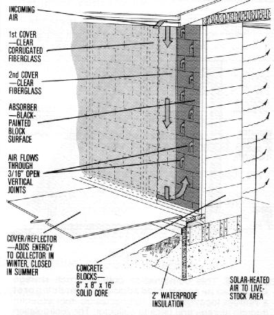
In-building storage. With an active system, a 16-inch thick, solid core, vertical block wall is often used-doubling as a unit for collecting and storing solar heat (Figure 8). This design was developed for use in livestock buildings by Kansas State University. Ventilation air passes through openings in the vertical block joints, picks up heat from the blocks and distributes it throughout the livestock building. The active. block wall unit can be used as the south sidewall in a new building or constructed as a stand-alone wall adjacent to an existing building.
Separate storage. An alternative to active system in-building storages is a separate storage area located near both collector and building. Storing and utilizing heat with a separate storage requires a dual circuit system--one circuit to transfer heat from collector to storage (`storage heating circuit') and another to transfer heat from storage to point of use (`building heating circuit').
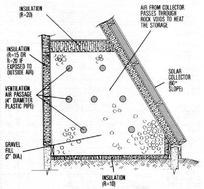
The storage heating circuit is almost always a closed circuit, with the heat transfer medium being recirculated between the collector and the storage. The building heating circuit, on the other hand, may be either a one-pass or a recirculating system. The most common type of one-pass system involves conveying in coming ventilation air by plastic ducts through a rock storage and then into a livestock shelter, while heated air from the collector is recirculated through the voids between the rocks (Figure 9).
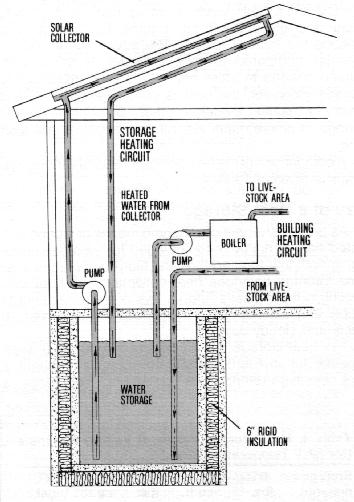
Dual recirculation systems are used with water- and some air-type collectors and storages. In Figure 10, an independent heating system is used to recirculate the water from storage to building floor, adding heat from the burner only if the storage temperature is not high enough. A clean-air application, such as farm shop heating, can also use dual recirculation systems.
(Note. Recirculating warm livestock, building air through rock or concrete block storage to recover heat is not recommended, however, because the storage material or air transfer ducts can pick up odors and become clogged with dust.)
Usually, pumps or fans in the storage heating circuit are operated only if the solar heated transfer medium (air or water) temperature is at least 10F higher than the storage temperature. Otherwise, stored heat could actually be lost through the poorly-insulated collector cover plates.
Heat storage units, whether used for active or passive systems, must be well-insulated on all sides. For below-ground installations, use insulation of R=15 for the top (unless you wish the storage area to heat a floor above) and waterproof insulation of at least R=10 for the sides and bottom. For above-ground units, insulate to at least R=20 for surfaces exposed to the air and to R=10 (using water proof insulation) for surfaces in contact with the ground.
The following examples illustrate how to calculate solar energy availability, facility heat requirements and heating system component sizes for common confinement swine housing situations in Indiana. The procedures would be the same for other types of livestock.
Example. A 28- by 80-foot, partly-slotted, monoslope 300-head capacity growing-finishing building located in central Indiana has a continuous row of 7-foot fiber-glass solar windows on the south sidewall (see Figure 2). What benefit, if any, is gained in winter (average inside temperature 60 F, outside temperature 20 F) by having solar windows rather than insulated vent doors?
1. Heat per sq. ft. of window. The heat input through a passive solar window is essentially the transmissivity of the window-about 80 percent for fiber-glass (Table 2); the window `angle' is 900 (vertical). Therefore, the average solar heat entering is (from Table 1, col. 7):
    December = 1017 x 80% = 814
    January  = 994  x 80% = 795
    February = 1119 x 80% = 895
			   ------
   Average heat available = 835 BTU/sq.ft.-day
Now we calculate heat loss attributable to solar windows compared with moderately well-insulated tilting ventilation doors. (Although the vent doors would be somewhat smaller than the solar windows, let's assume they are the same dimensions to simplify calculations.)
  1. Insulation R-values (from AE-95, Table 1).

    Solar windows = 0.9
    Vent doors, 1 1/2 in. batt insulation = 6.5

   2.Heat lost thru windows and doors =

                24 hr. x (Inside F - Outside F)
		          --------------------
                               R-value

    Solar window = 24 x (60-20) = 1067 BTU/sq.ft.-day
    heat loss     -------------
		      .9

    Vent door = 24 x (60-20) = 148 BTU/sq.ft.-day
    heat loss   ------------
		    6.5

    Heat loss diff. = 1067 - 148 = 919 BTU/sq.ft.-day
    (windows vs. doors)
1. Net value = Heat loss vs. doors - Solar heat available
= 919 - 835 = 84 BTU/sq.ft.-day (net loss)
While in this case, the solar windows lost more heat than they gained, passive solar systems do permit higher ventilation rates for improved odor control during daylight hours (with an excess of solar energy) when the operator is apt to be in the building. Consider using insulating glass or use insulated covers to decrease conduction heat loss through solar windows at night.
Example. A 24- by 60-foot, total-slotted, 20-sow farrowing house located in central Indiana has an 8-foot high ceiling and is oriented with the long axis east-west. How much temperature rise is possible during winter operation if the ventilation air is passed through an air-type, solid core concrete block, vertical wall collector adjacent to the south sidewall (see Figures 7 and 8)?
(Assume only cold weather and mild weather ventilation air will be moved through the collector. Hot weather ventilation air will be brought in directly from the outside as needed).
1.Cold weather-moisture control. Fan operated continuously for moisture removal at 10 cfm/sow x 20 sows = 200 cfm.
2.Cold weather-odor control. Fan operated as needed for odor control (and thermostatically controlled to prevent heat buildup) at 35 cfm/sow x 20 sows = 700 cfm.
3. Mild weather. Fan operated thermostatically at 80 cfm/sow x 20 sows = 1600 cfm.
1.Heat per sq. ft. of collector. Assuming the vertical concrete block wall collector is 50 percent efficient (Table 2), the amount of energy collected will be (from Table 1, col. 7):
    December = 1017 x 50% = 509
    January  =  994 x 50% = 497
    February = 1119 x 50% = 560
			   ----
  Average heat available = 522 BTU sq ft-day
Since storage is incorporated into the collector. this is the average amount of heat that can be collected during the day and then used as needed over the 24-hour period or stored for use on cloudy days.
2.Total heat available = Average heat available x collector area
=522 BTU/sq.ft.-day x (60 ft x 8 ft.) = 250,560 BTU/day
      Air weight = Ventilation rate x minutes/day
		   -------------------------------
                       Density of incoming air
1. At cold weather-moisture control rate
      Air = 200 cfm x 1440 min./day = 24,000 lb./day
      wt.   -----------------------
		12 cu.ft./lb.
2. At cold weather-odor control rate
      Air = 700 cfm x 1440 min./day  = 54,000 lb./day
      wt.  -------------------------
                12 cu.ft./lb.
3. At mild weather rate,
      Air = 1600 cfm x 1440 min./day = 192,000 lb./day
       wt.  --------------------
                 12 cu.ft./lb.
       Temp. =  Total heat available/day
       rise     ------------------------
	     Air weight x 0.241 BTU/lb.-F*

  *0.241 BTU/lb -F is the amount of heat energy required to raise
the temperature of a pound of air by 1 F
1. At cold weather-moisture control rate,
       Temp. =     250,560 BTU/day   = 43 F
       rise    ---------------------
	     24,000 lb./day x 0.241 BTU/lb.-F
2. At cold weather-odor control rate,
       Temp. =    250,560 BTU/day   = 12.4 F
       rise    ---------------------
              84,000 lb./day x 0.241 BTU/lb.-F
3. At mild weather rate.
       Temp. =     250,560 BTU/day    = 5.4 F
       rise     ---------------------
            192,000 lb./day x 0.241 BTU/lb.-F
In summer, the block wall collector has the additional benefit of cooling the daytime ventilation air. A 5-10 F temperature drop is possible by shading the collector surface with a reflective opaque cover and pulling the night ventilation air through the storage to cool if down. On many days, the cooling effect from the block wall storage permits operation at the mild weather ventilation rate. When the hot weather rate is required, incoming ventilation air should bypass the collector to prevent static pressure from becoming too high for the ventilation exhaust fans. Conventional slot air inlets should be designed and located as discussed in AE-96 to insure adequate environmental control during summer months.
                                    Cold weather rates
                                -----------------------------
                                   Moisture control on-
                                 -----------------------              Mild       Hot
   Type of animal                Fully    Partly   Solid   Odor      weather   weather
   or facility                  slotted  slotted   floor*  control   rates     rates
--------------------------------------------------------------------------------------
                                           cubic feet per minute
  Swine
    Sow and litter               10       17        20     35         80       325
    Pre-nursery pig (12-30 lb)   1.0      1.6       2      3.5       10        25
    Nursery pig (30-75 lb.)      1.5      2.5       3      5         15        35
    Growing pig (75-150 lb.)    35        5.5       7     10         24        75
    Finishing hog (150-220 lb.)   5        8        10     18         35       120
    Gestating sow (325 lb.)      6       10        12     20         40       150
    Boar (400 lb.)                7       12        14     24         50       180

  Dairy
    Cow                          16.5     28        33     50        130       600
    Calf                          5        8.5      10     16         25       150
    Milk room (total cfm)                            8                25        50
    Parlor (total cfm)                               8                25       100
--------------------------------------------------------------------------------------
* Increase moisture control ventilation rate by about 20 percent of
the solid floor value if invented furnaces are used.
Example: Using the same 20-sow farrowing house in the previous example, what would be the solar heating system requirements and heat gain benefits using a 60 degree slope, low-temperature collector and rock storage as shown in Figure 9? Assume the covered, suspended- plate collector is 8 feet by 60 feet and uses the sidewall for support. A squirrel-cage fan is located in a central plenum to recirculate the air through the storage heating circuit. Ventilation air entering the building passes through 4-inch diameter plastic pipe ducts embedded in the rock storage area to keep collection and distribution systems separate.
1. Heat per sq. ft. of collector. Assuming the 60 degree angle collector is 40 percent efficient (Table 2), the amount of energy collected will be (from Table 1, col. 6):
    December = 1082 x 40% = 433
    January  = 1081 x 40% = 432
    February = 1306 x 40% = 522
			    ----
  Average heat available =  462 BTU/sq.ft.-day
2. Total heat available = Average heat available x collector area
= 462 BTU/sq.ft.-day x (8 ft. x 60 ft.) = 221,760 BTU/day
3. Total collector air flow rate. Because the collector is most efficient at its maximum air flow rate, we will use the maximum recommended rate of 3 cfm/sq.ft. Thus, the collector's total flow rate is:
3 cfm/sq.ft. x (8 ft. x 60 ft.) = 1440 cfm.
1. Rock volume. Three days' storage is recommended for a low-temperature collector. Therefore, a rock volume sufficient for 3 days' storage is:
    Rock  =  Heat/day from collector x days storage
    volume  ----------------------------------------
	      Storage value of rock (from Table 4)

          =  221.760 BTU/day x 3 days   = 634 cu ft.
             ------------------------
                 1050 BTU. cu.ft
2. Rock size. Use smooth 1 1/2- to 3-inch diameter rock to maximize surface area and minimize pressure loss. Air flowing through a rock storage of this size for a distance of 30 feet should produce a pressure drop of about 3 inches of water static pressure. Excessively long distances or smaller diameter rock will increase the operational pressure of the fan.
3. Storage size and location. A rock pile 50 feet long, 3 feet wide and 4 feet high contains 600 cu.ft. of rock. This storage unit, including space for air plenums, can be constructed under the 60-foot-long collector next to the farrowing house. If the storage is divided into two 25-foot long sections and ventilation air enters the storage at each end, then the heated air will enter the livestock building from the center of the storage.
4. Air flow rate through storage. The storage heating circuit will have a total air flow rate of 1440 cfm (air flow from collector), or 720 cfm in each section of the storage. Therefore, the flow rate per unit of storage cross sectional area is:
720 cfm / (4 ft. x 3 ft.) = 60 cfm/sq.ft.
To prevent excessive operational pressure requirements for the recirculation fan, limit air flow through the rock storage to no more than 60 cfm/sq.ft. of cross sectional area and limit air flow distance to less than 30 feet.
5. Blower power capacity. A good rule of thumb is to provide 0.1 horsepower (hp) of blower capacity per square foot of storage cross section (maximum air flow length = 30 ft.). In this case, blower power requirements will be:
0.1 hp./sq ft. x (4 ft. x 3 ft.) = 1.2 hp.
1. Ducts needed. Ventilation air flow through the 4-inch ducts should be limited to 600 fpm to prevent excessive pressure loss. Therefore, maximum air flow in each pipe is about 50 cfm (0.088 sq.ft. area for 4-inch duct x 600 fpm = 52 cfm). Supplying the building with 700 cfm for the odor control ventilation rate (35 cfm/sow x 20 sows) would require a total of 14 pipes (700 cfm / 50 cfm) or seven 25-foot lengths in each of the two sections of the 50-foot long storage.
2. Heating capacity of the system. Since air heating through a rock-pipe interface occurs at a rate of about 4 BTU/ft.-F-hr. (96 BTU/sq.ft.-F-day), and the surface area of a 4-inch diameter pipe is about 1 sq.ft. per foot of duct length, then air in the pipe is heated at a rate of 96 BTU/sq.ft.-F-day. Assuming an average of 5F temperature difference between the rock storage and incoming ventilation air at all points along the path of air travel, the fourteen 25-foot pipe lengths are capable of transferring a total of:
    96 BTU/ft.-F-day x 5F temperature difference x
         14 pipes x 25 ft/pipe = 168,000 BTU/day
Thus, we see that, on the average, we are adding more heat to storage (221,760 BTU/day) than we are withdrawing (168,000 BTU/day). This allows for a storage heat loss of 24 percent. Although little is known about heat storage efficiencies, 20-25 percent loss from a well-insulated storage is probably not unreasonable.
If we find that 168,000 BTU/day does not give sufficient temperature rise to the incoming ventilation air (Step E), and if additional heat is available in storage, we could simply add more air ducts and lower the air flow rate through each to remove more heat from storage.
3. System design. Rock storages with separate collection and distribution systems. such as this one, should be designed on a `counterflow' principle-i.e., heated air from the collector flows through the storage in an opposite direction to the incoming ventilation air. Thus, even though there may only be a 5 F temperature difference between the ventilation air and the rock at any one point in the storage, there can be a significant temperature increase in both rock storage and ventilation air as the cold outside air progresses toward the building air inlet.
    Air weight = Vent rate/head x no. head x min./day
                 ---------------------------------------
		       Density of Incoming air
1. At cold weather-moisture control rate
    Air = 10 cfm x 20 sows x 1440 min./day  = 24,000 lb./hr
    wt    --------------------------------
	          12 cu.ft./ lb.
2. At cold weather-odor control rate
    Air = 35 cfm x 20 sows x 1440 min./day = 84,000 lb./day
    wt.   -------------------------------
                  12 cu.ft./lb.
* Assume only cold weather ventilation air will be moved through the heat storage. Mild and hot weather ventilation air will be brought in directly from outside as needed.
    Temp. = Heating capacity of ventilation system
     rise   ---------------------------------------
                Air weight x 0.241 BTU/lb.-F
1. At cold weather-moisture control rate,
     Temp. =      168,000 BTU/day           = 29 F
     rise    -------------------------
            24,000 lb./hr. x 0.241 BTU/lb.-F
2. At cold weather-odor control rate,
     Temp. =       168,000 BTU/day          = 8 F
     rise    ----------------------------
            84,000 lb./hr. x 0.241 BTU/lb.-F
Example. A 24- by 60-foot, 20-sow farrowing house, oriented with the long building axis east-west, has hot water floor heat. What would be the design requirements of a solar water heating system with a 45 slope (high-temperature) collector located on the roof and a water heat storage as shown in Figure 10?
1.Heat available per sq. ft of collector. The two-cover suspended plate collector mounted on a 450 slope roof has only a 35 percent efficiency (Table 2). (High-temperature collectors are less efficient than low-temperature ones.) Since floor heat will be needed 12 months out of the year, the daily energy collected will be (from Table 1, col.5):
    January   = 1034 x 35% = 362
    February  = 1287 x 35% = 450
    March     = 1550 x 35% = 542
    April     = 1553 x 35% = 544
    May       = 1631 x 35% = 571
    June      = 1696 x 35% = 594
    July      = 1747 x 35% = 611
    August    = 1818 x 35% = 636
    September = 1813 x 35% = 635
    October   = 1635 x 35% = 572
    November  = 1221 x 35% = 427
    December  = 1024 x 35% = 358
                            -----
    Average heat available = 525 BTU/sq.ft.-day
2. Heat available per sow and litter = Average heat available collector area per animal unit (from Table 3)
    = 525 BTU/sq.ft-day x 30 sq.ft.
    = 15,750 BTU/day or 656 BTU/hr
This amply meets the recommended 500 BTU/hr. minimum heat requirement in a farrowing house. However, it would be wise to use a supplemental boiler in case of continued cloudy weather after stored heat is used. Overhead radiant heat should also be supplied in the creep area (as pointed out in AE-96), as well as supplemental heat to warm the rest of the room.
3. Total heat available = Heat available per animal unit x no. animal units
    = 15,750 BTU/day x  20 sows and litters
    = 315,000 BTU/day
1. Solar collection rate. Solar collection takes place an average of 6 hours a day over the entire year, but only about 4 hours a day during winter. The heat collection rate per animal unit, therefore, should be designed for 4 hours:
          315,000 BTU/day   =  78,750 BTU/hr.
	  ---------------
             4 hr./day

 * From Table 4. the heat storage value for water is 1 BTU/lb.-F.
2. Water flow rate through collector. If water enters the collector at 95 F and leaves at 110 F, the wafer flow rate needed for this 150 temperature difference is:
            78,750 BTU/hr.   = 5250 lb./hr
           ---------------
           15 F x 1 BTU/lb-F

           = 5250 lb/hr. x 1 gal.
                          ------- = 630 gal/hr
                           833 lb.

           = 630 gal./hr
            ------------ =  10.5 gpm per sow and litter
             60 min/hr.
For our collector design, then, the total water flow rate needed is 10.5 gpm (or 1.1 gal./hr./sq.ft. of collector area), which is the value to use when sizing the pump and piping system for the collector.
1.Water volume. To provide for the variation in sun availability, heat storage is necessary. The amount of storage for high-temperature heat should be limited to 2, days.
    Water    Heat/day from collector x days storage
   ------ = ----------------------------------------
   volume    Storage value of water (from Table 4)**

            315,000 BTU/day x 2 days 21,000 lb.
          = ---------------------------------
             30 BTU/lb. (for 30 F rise)

          = 21,000 lb. /  8.33 lb./gal = 2521 gal.
          = 2521 gal. / 7.5 gal./cu.ft. = 336 cu.ft.

 **With high-temperature heat storage, it is doubtful that we will have
50 F usable temperature rise. therefore. we will use 60 percent of the
value in Table 4 (for a 30F temperature rise).
2. Storage dimensions. A water storage 8 feet deep, 6 feet wide and 7 feet long will contain 336 cu.ft. of water and thus meet our heat storage requirements.
In this publication, we have looked at solar energy collection and storage methods and the factors contributing to their effectiveness. Then we discussed what types of solar systems adapt well to what uses and gave examples of how to figure design requirements. Now let's briefly review some additional solar heat design and construction principles that should help insure an efficient, money-saving system.
Single copies of the following "Energy Management in Agriculture" publications are available to Indiana residents from their county Cooperative Extension Service office or by writing to Media Distribution Center, 301 S. Second St., Lafayette, IN 47905.
"Environmental Control for Livestock Housing" (AE-96)
"Insulating Livestock and Other Farm Buildings" (AE-95)
"Methane Generation from Livestock Waste" (AE-105)
"Natural Ventilation for Livestock Housing" (AE-97)
"Planning Farm Shops for Work and Energy Efficiency" (AE-104)
"Pit Ventilation Systems for Livestock Housing" (AE-98)
"Solar Heating for Home, Farm and Small Business" (AE-88)
"Solar Energy Heat Storage tor Home, Farm and Small Business" (AE-89)
"Troubleshooting Mechanical Ventilation Systems" (AE-100)
"Wind and Snow Control for the Farmstead" (AE-102)
"Worksheet for Sizing Livestock Housing Environmental Control Systems" (AE-109)
The following related publications are available from the Farm Building Plan Service, Agricultural Engineering Department, Purdue University, West Lafayette, IN 47907:
   "Swine Housing and Equipment Handbook" (MWPS-8)
   "Low Temperature and Solar Grain Drying Handbook" (MWPS-22)
   "Passive Solar Heated Swine Finishing Building" (Plan No 6274)
   "Solar Heat Rock Storage" (Plan No 81172)
   "Solar Active Wall Collector/Storage" (Plan No 81171)
   "48' Solar Machine Shed and Shop" (Plan No 81901)
   "20-Sow' Solar Farrowing House" (Plan No 81902)
New 8/80
Cooperative Extension work in Agriculture and Home Economics, state of Indiana, Purdue University, and U.S. Department of Agriculture cooperating; HA. Wadsworth, Director, West Lafayette. IN. Issued in furtherance of the acts of May 8 and June 30, 1914. Purdue University Cooperative Extension Service is an equal opportunity/equal access institution.